English
Modern electronic products need smaller circuit boards, more functional components, repeatable assembly, and predictable production costs. Surface Mount Technology (SMT) is central to meeting those requirements. It allows electronic components to be mounted directly onto PCB surface pads, making automated, high-density assembly practical for products ranging from consumer electronics to industrial controls and communications equipment.
For most new electronic designs, SMT should be the starting point—not an automatic choice for every component, but the default assembly process to evaluate first. The right result still depends on component package, board layout, thermal requirements, mechanical stress, inspection access, and production volume. A well-designed SMT process can deliver speed and consistency; a poorly prepared design can turn those advantages into solder defects, rework, and delayed launches.
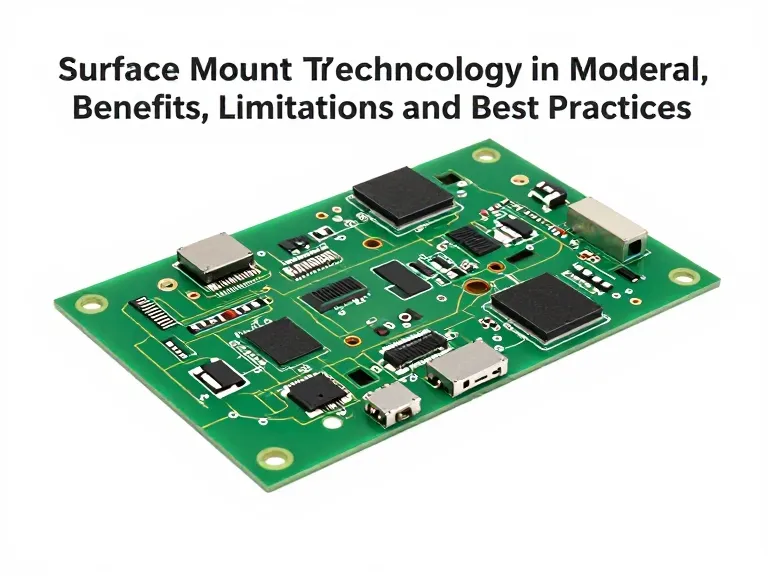
Quick Answer: Is Surface Mount Technology Right for Your PCB?
Choose SMT when your product needs compact dimensions, high component density, automated placement, and repeatable production. It is particularly suitable for consumer devices, communications hardware, computing products, industrial controllers, and many automotive electronic assemblies. Use through-hole assembly selectively when a component needs strong mechanical anchoring, must tolerate substantial insertion or extraction forces, or is not available in a suitable surface-mount package.
In most professional situations, the strongest solution is not to insist on SMT for every part. It is to design an SMT-first board and introduce through-hole or other specialized assembly steps only where the engineering requirements justify them.
What Is Surface Mount Technology?
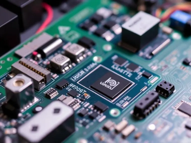
Surface Mount Technology is an electronics assembly method in which components are placed and soldered onto conductive pads on a printed circuit board rather than relying on component leads inserted through drilled holes. The components are known as surface-mount devices (SMDs), and the assembled board is commonly called an SMT PCBA.
The process normally begins with solder paste deposited onto PCB pads through a stencil. Automated pick-and-place equipment positions components on the paste, and a controlled reflow oven melts the solder to form electrical and mechanical connections. Depending on the board and component mix, the assembly may then undergo automated optical inspection, X-ray inspection, electrical testing, and functional testing.
SMT is not simply a faster way to attach parts. It changes how a circuit board is designed, manufactured, inspected, and repaired. Pad geometry, solder-mask definition, component spacing, thermal management, and the assembly sequence all influence the finished board's quality.
| Decision factor | What SMT offers | Practical recommendation |
|---|---|---|
| Board size | Supports compact layouts and high component density. | Use SMT when space and weight are major constraints. |
| Production speed | Automated placement supports repeatable, high-throughput assembly. | Confirm feeder setup, line capacity, and component availability before committing to delivery dates. |
| Manufacturing cost | Can reduce manual insertion and handling at suitable volumes. | Compare total assembly cost, including tooling, setup, inspection, and rework—not just placement price. |
| Mechanical loading | Works well for many standard components but not every high-stress interface. | Evaluate connectors, switches, and heavy components individually. |
| Fine-pitch packages | Supports dense IC packages, including selected BGA and QFN designs. | Plan inspection and X-ray access where hidden solder joints are used. |
| Prototype production | Can support prototypes as well as volume production. | Ask whether stencil, setup, and engineering charges apply to small batches. |
How the Surface Mount Technology Assembly Process Works
A reliable SMT process is a controlled sequence, not merely a board passing through a placement machine. Each stage influences downstream quality. When defects appear, the fastest solution is often to identify the process step that introduced them instead of adding inspection at the end.
1. PCB and manufacturing-data review
Before assembly, the manufacturer checks the PCB design files, bill of materials (BOM), component footprints, polarity markings, package availability, and assembly drawings. Gerber or other fabrication data, drill files, centroid or pick-and-place data, and the BOM must agree. Inconsistent part numbers or missing orientation information can cause delays before the first board is assembled.
For a new product, we recommend a design-for-manufacturing (DFM) and design-for-assembly (DFA) review before releasing the build. Resolve footprint and spacing issues while changes are still inexpensive.
2. Solder paste printing
A stencil transfers controlled quantities of solder paste onto the PCB pads. The paste volume and position affect joint formation, especially for fine-pitch ICs, small passive components, and packages with exposed thermal pads. Poor stencil alignment, clogged apertures, inconsistent paste condition, or inadequate board support can cause insufficient solder, bridging, and component movement.
3. Automated component placement
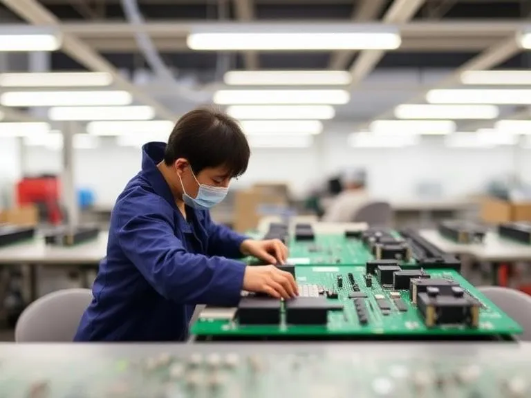
Pick-and-place machines position resistors, capacitors, integrated circuits, connectors, and other SMDs on the printed paste. Placement accuracy, nozzle selection, component recognition, feeder condition, and correct rotation all matter. Before production, the assembly team should verify polarity-sensitive components and confirm that the loaded reels match the approved BOM.
4. Reflow soldering
The populated board passes through a reflow oven. A controlled thermal profile activates the flux, melts the solder, and allows joints to form before the assembly cools. The profile must match the solder paste, PCB thermal mass, component limits, and board construction. A generic oven profile is not a substitute for process validation.
5. Inspection and testing
Automated optical inspection (AOI) can identify visible placement and soldering defects. X-ray inspection is often appropriate for hidden joints under BGA packages and other components whose solder connections cannot be seen from the surface. Electrical testing and functional testing provide different evidence: one checks circuit connections or electrical characteristics, while the other evaluates whether the product performs as intended.
Not every board requires every inspection method. The correct inspection plan depends on product risk, package types, customer requirements, and applicable industry standards.
Key Benefits of Surface Mount Technology in Modern PCBA Manufacturing
Higher component density and smaller products
Because SMDs do not need leads inserted through the board, designers can place components on one or both sides of a PCB and use compact packages. This is a major advantage for portable electronics, communications devices, embedded systems, and products where enclosure size is fixed.
SMT does not eliminate layout constraints. Fine-pitch packages still need appropriate clearances, solder-mask design, routing space, and thermal management. For very dense designs, the PCB itself may also require advanced construction such as HDI PCB technology. Higher density is useful only when the complete board can be fabricated and assembled reliably.
Automation and repeatability
Automated printing, placement, and reflow reduce dependence on manual component insertion for compatible designs. Once the process is qualified, automation can improve repeatability across production lots and reduce handling variation. For commercial users, this can make output planning more predictable.
Automation does not guarantee defect-free production. Incorrect BOM data, unsuitable footprints, poor paste control, and inadequate process monitoring can produce the same defect repeatedly at high speed. The benefit comes from a controlled process, not from machine automation alone.
Potentially lower assembly cost
SMT can reduce manual labor and support efficient production when component packages and board design are appropriate. However, the lowest quoted placement price is not necessarily the lowest total cost. Stencil charges, programming, feeder setup, inspection, testing, scrap, and rework all affect the final cost per good board.
For prototypes and small batches, setup costs may be a substantial share of the total. For recurring production, the economics often improve when the same design and component set can be built consistently. Ask suppliers to separate one-time setup charges from recurring unit costs.
Access to modern component packages
Many current microcontrollers, memory devices, power-management ICs, sensors, and wireless components are available primarily in surface-mount packages. SMT is therefore a practical requirement for many modern electronic designs rather than an optional manufacturing upgrade.
For advanced computing or high-speed communications products, package choice must be considered alongside signal integrity, power delivery, and thermal behavior. A suitable PCB stack-up, such as a purpose-designed high-speed PCB, may be as important as the assembly process.
Limitations of Surface Mount Technology and How to Manage Them
SMT is versatile, but it is not universally superior. A production plan that ignores its limitations can create expensive failures or make field repair unnecessarily difficult.
Mechanical stress on selected components
Surface-mounted connectors, switches, and heavy components may experience stress from insertion forces, vibration, drops, or repeated use. The correct response is not automatically to replace them with through-hole parts. First assess the load path, component design, solder-joint geometry, board support, enclosure, and expected operating environment. Through-hole anchoring or a mechanical bracket may be justified where the stress analysis supports it.
Inspection challenges with hidden joints
BGA packages and some bottom-terminated components have solder joints that cannot be inspected visually after assembly. AOI alone cannot confirm the condition of every hidden joint. Depending on risk and acceptance criteria, X-ray inspection, process monitoring, test coupons, and functional validation may be needed.
Rework requires appropriate equipment and skill
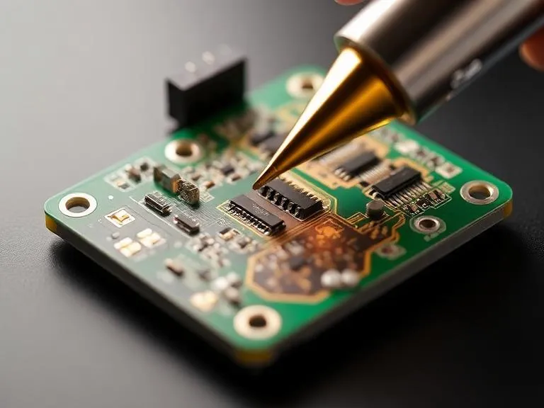
Small components and fine-pitch packages can be damaged by uncontrolled heat, pad lifting, or repeated rework. For prototypes, a qualified rework station and trained operator may be sufficient. For high-value or safety-critical assemblies, rework procedures should be documented and validated rather than improvised on the production floor.
Thermal and layout constraints remain
SMT packages can be compact, but heat dissipation depends on package design, copper area, thermal vias, airflow, and enclosure conditions. A small footprint does not mean a component can handle unlimited power. Power devices should be evaluated using the manufacturer's thermal data and the actual operating conditions.
Practical rule: Do not select SMT simply because the parts are smaller. Select it when the electrical, thermal, mechanical, and manufacturing requirements can all be satisfied by the proposed package and assembly process.
SMT vs. Through-Hole Assembly: Which Should You Choose?
SMT and through-hole technology (THT) are complementary assembly methods. SMT is generally better suited to dense, automated electronics, while through-hole assembly remains valuable for components whose lead structure or mechanical role benefits from insertion through drilled PCB holes. Mixed-technology boards are common when the design requires both.
| Criteria | Surface Mount Technology | Through-Hole Technology | Preferred decision |
|---|---|---|---|
| Board footprint | Usually smaller; supports compact packages. | Requires drilled holes and lead clearance. | SMT for space-constrained designs. |
| Automation | Well suited to automated placement and reflow. | May involve manual insertion or specialized insertion equipment, followed by soldering. | SMT for high-volume compatible designs. |
| Mechanical anchoring | Depends on pad design, package, and board support. | Leads through the board can provide stronger anchoring for selected parts. | Evaluate THT for high-force connectors or mechanically loaded components. |
| Component availability | Broad range of modern ICs and passive components. | Useful for selected connectors, legacy parts, and leaded components. | Follow actual component availability and lifecycle plans. |
| Repair and rework | Fine-pitch and hidden-joint packages may require specialized tools. | Some leaded components are easier to replace, depending on the board. | Base the decision on service strategy and package complexity. |
| Typical cost drivers | Stencil, placement setup, inspection, component mix, and rework. | Drilling, insertion labor, wave/selective soldering, and inspection. | Compare total cost for the actual BOM and batch size. |
| Best fit | Compact consumer, computing, communications, and industrial electronics. | Selected high-stress components, legacy assemblies, and specialized designs. | Use SMT as the baseline; mix technologies when justified. |
For a new controller with a microcontroller, memory, passive components, and a few board-mounted connectors, an SMT-first design is usually sensible. If a connector will experience frequent cable insertion or substantial mechanical loading, evaluate a through-hole version or additional mechanical support. The decision should be based on the forces the product will experience—not on a blanket belief that one technology is always more reliable.
Pros and Cons of Surface Mount Technology
| Pros | Cons |
|---|---|
| Supports compact layouts and high component density. | Fine-pitch packages demand accurate design data and process control. |
| Automated placement can improve repeatability and production throughput. | Setup and programming costs can be significant for very small batches. |
| Provides access to many modern IC and passive component packages. | Some hidden solder joints need X-ray or other suitable verification. |
| Can reduce manual insertion labor in suitable production runs. | Rework can require specialized equipment and trained technicians. |
| Supports assembly on one or both PCB sides. | Mechanically stressed or heavy components may need additional support or THT. |
| Scales from prototypes to larger production when the process is configured appropriately. | Actual cost and lead time depend on component sourcing, line capacity, inspection, and testing. |
Our recommendation is to judge SMT by the performance of the complete manufacturing process. A fast line is valuable, but not if the design generates recurring solder defects or the inspection plan misses the failure modes that matter to the product.
Best Applications for Surface Mount Technology
Consumer electronics and connected devices
Wearables, smart-home equipment, portable products, and compact control boards often benefit from SMT's component density. If the enclosure is small, begin with an SMT layout and validate antenna clearance, thermal conditions, and connector durability before finalizing the board.
Computing and communications equipment
Routers, networking devices, embedded computers, and storage electronics use compact IC packages and dense routing. These products may require careful control of signal integrity, impedance, grounding, and thermal design. SMT supports the assembly strategy, but it cannot compensate for a poorly designed PCB. Coordinate board fabrication and assembly early, particularly for complex stack-ups and fine-pitch components.
For designs that integrate processors or high-density packages, assess whether an advanced construction such as FC-CSP PCB is appropriate to the selected component and electrical requirements. Package and board decisions should be made together.
Industrial and automotive electronics
Industrial controllers, sensors, power monitoring boards, and automotive modules can use SMT effectively, but environmental and reliability requirements should drive the process plan. Temperature cycling, vibration, moisture, contamination, and service access may influence component selection, coating, board support, inspection, and qualification testing.
For automotive-related products, confirm the customer's required quality system, traceability, component qualification, and applicable product-specific requirements. Do not assume that using SMT automatically makes a board suitable for automotive service.
Medical, laboratory, and instrumentation products
SMT can support compact instruments and data-acquisition devices, but the appropriate quality controls depend on the device's intended use and regulatory classification. Documented process controls, component traceability, risk-based testing, and design verification are more important than simply choosing the newest package style.
PCB Design and Component Sourcing Considerations Before SMT Assembly
Assembly quality is partly determined before the PCB reaches the production line. A manufacturer can help identify risks, but the most cost-effective approach is to resolve avoidable design and sourcing problems before tooling and production quantities are committed.
Review footprints, polarity, and component orientation
Check land patterns against component datasheets and relevant package recommendations. Confirm polarity marks, pin-one indicators, connector orientation, and the position of exposed thermal pads. Ensure the assembly drawing and centroid data reflect the approved revision. Revision mismatch between the PCB, BOM, and pick-and-place file is a preventable source of rework.
Assess component availability and approved alternatives
A technically suitable component may be difficult to obtain or approaching end of life. Work with the assembly provider to review lead times, manufacturer part numbers, lifecycle status, and approved substitutes. Do not permit substitutions based only on similar package dimensions: electrical ratings, tolerances, thermal behavior, firmware compatibility, and certification requirements may differ.
For projects that need coordinated procurement, PCBA components sourcing can help align the BOM with the assembly plan. Ask how the supplier verifies part identity, manages customer-supplied materials, and records lot or date-code information where required.
Choose the PCB construction and surface finish deliberately
Board material, copper weight, layer count, thickness, and surface finish affect fabrication and assembly. For many general-purpose designs, FR4 PCB construction is a practical starting point. High-speed, flexible, high-temperature, or high-density applications may require a different construction or additional engineering review.
The surface finish must also suit the component pitch, storage conditions, assembly process, and cost target. Lead-free HASL, OSP, immersion silver, and other finishes have different process characteristics and handling considerations. Compare them against the actual requirements rather than assuming one finish is universally best.
Plan the prototype as a learning stage
A prototype build should verify more than whether the board powers on. Use it to validate assembly data, package compatibility, test access, connector fit, thermal performance, and the adequacy of the inspection plan. If the design is still changing, a PCB prototype service can help expose manufacturing issues before a larger order is released.
Quality Control, RoHS, and Industry Standards in SMT Manufacturing
SMT quality depends on documented requirements and measurable process controls. A supplier's statement that it follows “industry standards” is not enough on its own. Buyers should identify which standards apply to their product, what acceptance criteria will be used, and which inspection and test records will be provided.
IPC workmanship and acceptance criteria
IPC standards are widely used in electronics manufacturing to define requirements for materials, assembly processes, and finished-board acceptability. The applicable document and class should be agreed upon for the project; a higher class is not automatically necessary for every commercial product. Confirm the exact revision, acceptance criteria, and any customer-specific additions in the purchase specification.
RoHS and material compliance
Where required by the destination market or customer, verify compliance with applicable restrictions on hazardous substances, including the relevant RoHS requirements. Lead-free soldering requires an appropriate process and material selection; it should not be treated as a simple checkbox. Confirm material declarations and supporting documentation for the actual parts and manufacturing route.
Inspection should reflect the failure risk
AOI is useful for visible placement and soldering defects, but it cannot inspect every hidden joint. X-ray can help evaluate selected packages, while in-circuit and functional tests address different electrical and operational questions. For high-risk applications, a documented control plan should explain what each test can detect and what it cannot.
We recommend agreeing on inspection coverage before production begins. It is more effective to design a suitable verification plan than to discover after shipment that the chosen inspection method could not detect the defect that occurred.
How to Choose an SMT PCB Assembly Manufacturer
The right SMT partner should be able to explain how it will build, inspect, and verify your board—not just quote a per-board price. A capable supplier connects engineering review, component sourcing, process setup, quality control, and delivery planning into one manufacturing workflow.
Ask about equipment and actual package capability
Confirm whether the production line can handle your smallest passive components, fine-pitch ICs, board dimensions, double-sided assembly, and any BGA or QFN packages in the design. Request clarification on which inspection methods are available in-house and which are outsourced. Equipment lists are useful, but the supplier's experience with your package mix matters more.
Evaluate engineering support and communication
A strong partner flags incomplete BOMs, incompatible footprints, obsolete components, and test-access problems before they become production delays. Ask who reviews the files, how engineering questions are resolved, how revisions are controlled, and what information is included in the first-article report.
Check sourcing controls and traceability
Discuss whether the manufacturer can source components, accept customer-supplied parts, or work with a hybrid procurement model. Clarify how it handles shortages, substitutions, counterfeit-risk controls, and material records. If a component change requires customer approval, make that requirement explicit in writing.
Look for a realistic prototype-to-production path
Low-volume builds should not be treated as an afterthought. Confirm whether the supplier can support prototypes, engineering changes, pilot runs, and repeat orders with consistent documentation. 365PCB's SMT PCB assembly services are presented as supporting prototype through volume production, including fine-pitch and BGA-capable assemblies, with no minimum order quantity stated for the service. Buyers should still confirm the current scope, applicable setup charges, component availability, and delivery schedule for their own BOM.
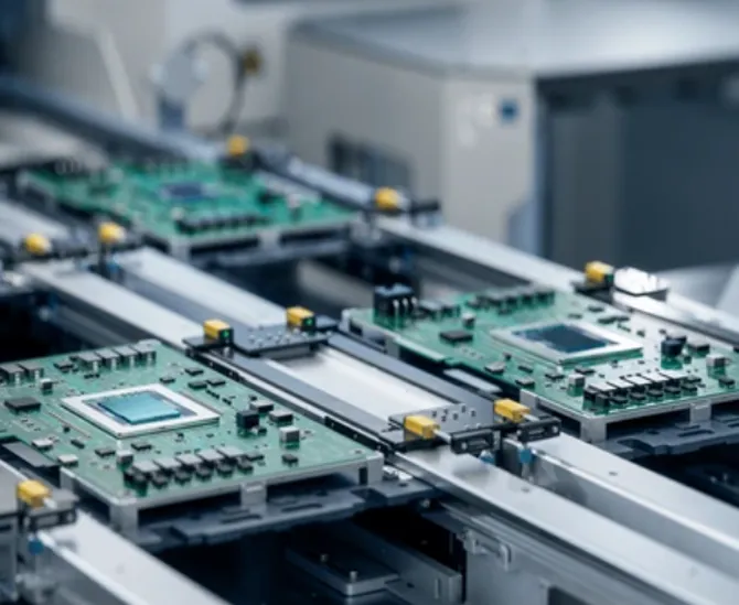
SMT PCB Assembly Services from 365PCB
365PCB offers SMT PCB assembly for projects ranging from prototypes to volume production, with automated placement and support for a range of component packages. The service may be worth evaluating when you need a manufacturing partner to coordinate board assembly and component requirements rather than managing each step separately.
Before ordering, provide the Gerber or fabrication package, BOM with manufacturer part numbers, centroid data, assembly drawings, board quantity, target delivery date, and required inspection or testing criteria. Ask for a quotation that clearly separates setup, materials, assembly, inspection, and any additional services.
SMT Cost-Benefit Analysis: When Is It Worth Upgrading?
SMT can lower assembly costs and improve repeatability, but the result depends on the design and production plan. The correct comparison is the cost per accepted, tested board—not the raw assembly price alone.
For prototypes and small batches
Setup, stencil, programming, and engineering review can represent a large portion of a small order. Even so, SMT is often the right choice when the design uses surface-mount ICs or needs to reflect the intended production process. A prototype built with a different assembly approach may not reveal the same manufacturability issues.
To control costs, freeze the BOM before ordering, confirm all components are available, and resolve footprint questions early. If multiple design revisions are expected, agree on how stencil or programming changes will be charged.
For recurring commercial production
For repeated builds, automated placement can improve throughput and consistency. Savings become more meaningful when the board design, component mix, and process settings are stable. The business case weakens when frequent engineering changes, shortages, or preventable defects create repeated setup work and scrap.
For complex boards and fine-pitch packages
Higher-density designs may justify a more capable assembly process, but additional inspection or specialized handling can increase cost. Compare the incremental cost against the product's reliability requirements, failure consequences, and expected production life. For hidden-joint packages, it is usually better to budget for suitable verification than to omit it solely to reach a lower quotation.
| Project situation | Recommended approach | Where to spend carefully |
|---|---|---|
| Early-stage prototype | Use SMT if it reflects the final design; prioritize fast engineering feedback. | Avoid unnecessary options, but retain essential inspection and functional tests. |
| Stable recurring product | Standardize BOM, revisions, approved alternates, and process documentation. | Optimize setup and procurement without weakening quality controls. |
| Fine-pitch or BGA-heavy board | Confirm line capability and define suitable hidden-joint inspection. | Budget for X-ray or other risk-appropriate verification. |
| High mechanical stress | Review package choice, board support, and mixed SMT/THT options. | Invest in mechanical validation rather than relying on solder joints alone. |
| Cost-sensitive low volume | Compare complete quotes from suppliers using the same BOM and test scope. | Separate one-time charges from recurring unit costs. |
For a project that has outgrown a manual assembly approach, upgrade to automated SMT when the component mix, repeat-order demand, or quality targets justify it. Do not upgrade purely to claim that the process is more advanced. The upgrade must solve a measurable problem, such as excessive assembly time, inconsistent placement, insufficient density, or the need to use packages that manual methods cannot reliably support.
Common Surface Mount Technology Mistakes to Avoid
1. Treating the BOM as a shopping list rather than a controlled document
A BOM should include manufacturer part numbers, quantities, reference designators, and approved alternatives where applicable. Generic descriptions such as “10 kΩ resistor” are not enough when tolerance, package size, power rating, or temperature coefficient matters. Keep the BOM revision aligned with the PCB and assembly data.
2. Assuming AOI proves every joint is sound
AOI is valuable, but it cannot confirm all hidden solder connections or functional behavior. Match inspection methods to package type and risk. For boards with BGA components, ask whether X-ray inspection is appropriate and how defects will be evaluated.
3. Ignoring thermal and mechanical conditions
A component that works on a bench may fail in an enclosed product exposed to heat or vibration. Review the real operating environment, not just nominal electrical specifications. Add mechanical support or use through-hole components where engineering evidence supports that decision.
4. Selecting a supplier by unit price alone
Two quotes are not comparable if one includes component sourcing, AOI, X-ray, electrical testing, and traceability while the other excludes them. Normalize the quotation scope before choosing. A low initial price can become expensive if defects, missing documentation, or schedule slippage require additional work.
5. Skipping a manufacturing review before production
Late changes to footprints, component substitutions, and assembly orientation can affect cost and schedule. Request a DFM/DFA review and first-article confirmation before releasing a larger order. For more complex products, align the PCB fabrication and assembly requirements from the beginning rather than treating them as separate decisions.
Expert Recommendation: Use SMT as the Baseline, Not a Blanket Rule
For most new electronic products, Surface Mount Technology is the sensible baseline because it supports compact layouts, automated production, and the component packages used across modern electronics. The important qualification is that SMT must be matched to the actual product, not selected on reputation alone.
We recommend starting with four questions:
Does the component mix require surface-mount packages or high-density placement?
Will the product experience mechanical, thermal, or environmental stresses that affect package choice?
Can the proposed manufacturer build and inspect the package mix using an agreed, documented process?
Does the quotation include the sourcing, inspection, testing, and traceability the product actually needs?
If the answers are clear, SMT can provide a practical path from prototype to repeat production. If the design includes high-stress connectors or components that are poorly suited to surface mounting, use a mixed-technology strategy. That is not a compromise; it is often the better engineering decision.
For buyers evaluating 365PCB, prepare a complete manufacturing package and request confirmation of assembly capability, inspection coverage, lead time, component sourcing arrangements, and total cost. A supplier that asks detailed questions before quoting is generally more useful than one that promises an attractive price without understanding the board.
Frequently Asked Questions About Surface Mount Technology
What is Surface Mount Technology used for?
Surface Mount Technology is used to assemble electronic components directly onto PCB surface pads. It is common in consumer electronics, computing, communications, industrial controls, automotive modules, and many other electronic products that need compact layouts and automated manufacturing.
Is SMT better than through-hole assembly?
Neither process is universally better. SMT is generally preferred for compact designs, high component density, and automated placement. Through-hole assembly can be more suitable for selected components exposed to high mechanical loads or designs that require leaded packages. Mixed SMT and through-hole assembly is often the most practical option.
Does SMT reduce PCB manufacturing cost?
It can reduce assembly labor and improve throughput for compatible designs, particularly in recurring production. Total cost still depends on setup, stencil, component sourcing, inspection, testing, defect rates, and batch size. Compare cost per accepted board rather than placement price alone.
Can SMT be used for PCB prototypes?
Yes. SMT is suitable for prototypes when it reflects the intended production design or uses surface-mount components that cannot be assembled otherwise. Confirm setup fees, stencil requirements, component availability, and the scope of inspection before placing the order.
What quality checks are important for SMT PCB assembly?
Common checks include solder paste and placement process controls, automated optical inspection, and electrical or functional testing. X-ray inspection may be appropriate for hidden solder joints such as those under BGA packages. The right combination depends on package types, customer requirements, and product risk.
What files are needed for an SMT assembly quotation?
Typically, provide PCB fabrication data, a BOM with manufacturer part numbers, centroid or pick-and-place files, assembly drawings, quantity, target schedule, and testing or inspection requirements. If components will be customer-supplied, state that clearly and identify any special handling or traceability needs.
Does using SMT automatically make a product more reliable?
No. Reliability depends on component selection, PCB layout, solder-joint design, process control, inspection, environmental conditions, and product validation. SMT provides manufacturing advantages, but reliability must be designed and verified.
References
The following authoritative resources provide additional context for electronics assembly quality and material compliance. Confirm the current editions and applicable requirements for your specific product.
IPC — Association Connecting Electronics Industries. Industry standards and resources covering electronics design, assembly, and acceptability.
European Commission — Restriction of Hazardous Substances (RoHS) Directive. Official information on restrictions applying to electrical and electronic equipment.
National Institute of Standards and Technology (NIST). Resources on measurement science, manufacturing, and quality-related technical practices.