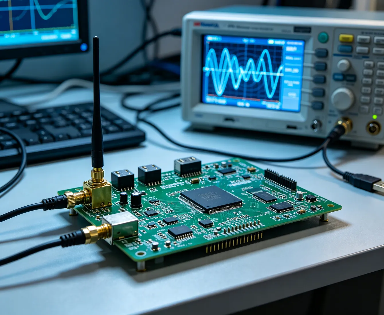
Before selecting a processor, drawing a circuit, laying out a PCB, writing firmware, or building a prototype, the product concept must first answer a more fundamental set of questions:
What exactly must the product do?
Is the proposed architecture technically feasible?
Can the required performance be achieved within the available size, power, thermal, cost, reliability, regulatory, and manufacturing constraints?
Can the product be built once — and can it later be manufactured reliably at scale?
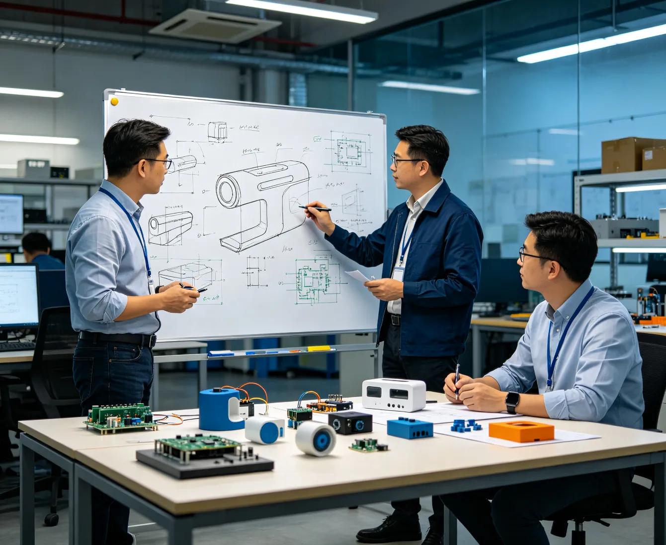
365PCB Product Concept & Feasibility Engineering transforms an initial product idea into a technically defined, risk-assessed, and development-ready engineering program.
Our objective is not simply to determine whether an idea is possible.
We determine how it should be engineered.
One of the most expensive mistakes in electronic product development is beginning detailed design before the system architecture has been properly defined.
A processor may be selected before actual computing requirements are understood.
A wireless technology may be chosen before range, certification, antenna space, and power consumption are evaluated.
A battery may be selected before peak current, thermal behavior, charging strategy, and required runtime are modeled.
A PCB architecture may be committed before mechanical constraints are stable.
A prototype may work in the laboratory but become too expensive, difficult to certify, thermally unstable, or impossible to manufacture reliably.
365PCB approaches feasibility engineering from the system level.
We evaluate the interaction between:
Performance
Electronics
Firmware
Connectivity
Power
Mechanical
Thermal
Reliability
Supply Chain
Manufacturing
Cost
before those constraints become expensive redesigns.
The Goal Is Not to Start Design Faster.
The Goal Is to Start the Right Design.
Product Requirements Definition
Customers often begin with a product concept rather than a complete engineering specification.
The starting information may be:
Our engineering process converts these inputs into structured technical requirements.
Depending on the project, requirements can include:
What must the product actually do?
Processing speed, measurement accuracy, bandwidth, latency, control performance, communication range, response time, or other measurable targets.
Input power, operating voltage, current, battery requirements, interfaces, signals, sensors, actuators, and loads.
Temperature, humidity, vibration, shock, ingress, outdoor operation, contamination, or other environmental conditions.
Dimensions, weight, mounting, connectors, enclosure, user interfaces, installation constraints, and structural requirements.
Ethernet, Wi-Fi, Bluetooth, BLE, Thread, Zigbee, LoRa, cellular, GNSS, CAN, RS485, USB, PCIe, or application-specific interfaces.
Expected operating life, duty cycle, service conditions, maintenance requirements, and acceptable failure risk.
Prototype quantity, target annual volume, production geography, assembly constraints, test strategy, traceability, and expected scale.
Target BOM cost, target manufacturing cost, development schedule, lifecycle expectations, and supply-chain constraints.
A requirement that cannot eventually be verified is usually not yet a sufficiently defined engineering requirement.
Define What Success Means Before Designing the Product.
System Architecture Engineering
Once product requirements are understood, the next task is to define the system architecture.
This establishes how the product will be divided into functional subsystems and how those subsystems interact.
Depending on the project, the architecture may include:
Analog · Digital · Optical · Motion · Environmental · Position · Current · Voltage
Connectivity
Wired · Wireless · Industrial Networks · Cloud Connectivity
Power
Power Input · Regulation · Battery · Charging · Protection · Power Distribution
Control
Motor Control · Actuator Control · Real-Time Control · Safety Logic
Human Interface
Display · Touch · Buttons · LEDs · Audio · HMI
Mechanical
PCB Form Factor · Enclosure · Connector Locations · Mounting
Thermal
Heat Sources · Thermal Paths · Cooling Strategy · Temperature Limits
Software
Bootloader · BSP · Drivers · RTOS · Linux · Application Firmware · Connectivity Stack
Architecture decisions made here strongly influence almost everything that follows.
Architecture Determines the Design Space.
Architecture Trade Studies
Advanced engineering does not simply choose the first architecture that appears workable.
Alternative approaches should be evaluated against the complete product requirements.
For example:
MCU vs MPU
MCU vs FPGA
FPGA vs SoC
Linux vs RTOS
Wi-Fi vs Cellular
BLE vs Thread
Discrete Power vs Integrated PMIC
Custom RF vs Certified Wireless Module
Single-Board vs Multi-Board Architecture
Passive Cooling vs Active Cooling
Battery vs External Power
Each architecture can affect:
Performance
Cost
Power
Thermal behavior
PCB complexity
Development time
Firmware complexity
Component availability
Certification
Reliability
Manufacturability
Product lifecycle
365PCB engineering evaluates these interactions before architecture lock.
The Best Component Is Not Always the Best System Decision.
Compute Architecture Feasibility
Modern electronic products may require anything from a small ultra-low-power MCU to an advanced multicore application processor, FPGA, DSP, or AI accelerator.
Feasibility engineering can evaluate:
Required processing workload
Real-time behavior
Interrupt latency
Control-loop requirements
Memory bandwidth
RAM and storage
Peripheral requirements
Hardware acceleration
FPGA logic requirements
DSP requirements
Edge-AI inference requirements
Video-processing requirements
Operating-system requirements
Boot-time requirements
Security requirements
Power consumption
Thermal limits
Long-term component availability
The objective is not to specify the most powerful processor available.
It is to select the architecture with sufficient margin for the product without introducing unnecessary cost, power, thermal, or development complexity.
Analog, Sensor & Measurement Feasibility
For sensing, measurement, industrial, instrumentation, medical-adjacent, energy, and control products, system performance may depend heavily on the analog signal chain.
Early feasibility analysis can evaluate:
Important considerations can include:
Signal amplitude
Dynamic range
Signal-to-noise ratio
ADC resolution
Effective number of bits
Sampling rate
Analog bandwidth
Offset
Drift
Reference accuracy
Sensor accuracy
Calibration
Noise sources
Grounding
Isolation
EMI susceptibility
At higher precision levels, simply selecting a high-resolution ADC does not guarantee a high-resolution measurement system.
System Accuracy Is the Result of the Entire Signal Chain.
RF, Wireless & Antenna Feasibility
Wireless product feasibility requires much more than choosing a radio IC.
The architecture can involve:
A wireless product can function perfectly on an open development board and perform very differently once the electronics are installed inside the final enclosure.
That is why:
RF Architecture, PCB Design, Antenna Design, Mechanical Design, and Certification Must Be Considered Together.
Power Architecture & Energy Budget
Every electronic product has an energy architecture.
For battery-powered and power-dense products, this can become one of the defining engineering constraints.
Feasibility work can include:
Power-tree architecture
Supply-rail definition
Peak-current analysis
Average power
Sleep power
Battery capacity
Runtime estimates
Charging architecture
DC/DC topology
LDO requirements
Conversion efficiency
Inrush current
Sequencing
Protection
Power-path management
Thermal dissipation
Fault conditions
For sophisticated products, engineering can build a preliminary:
showing how power is distributed between subsystems and whether the proposed architecture can meet runtime and thermal objectives.
Thermal Feasibility
High-performance electronics increasingly reach their limits not because additional computing performance is impossible, but because heat cannot be removed efficiently within the available mechanical envelope.
Early thermal feasibility considers:
Potential thermal bottlenecks should be identified before PCB and enclosure architecture are frozen.
Power Density Is a System Architecture Constraint.
Interface & Connectivity Architecture
Complex products may integrate multiple internal and external interfaces.
Examples can include:
UART
SPI
I²C
USB
Ethernet
CAN / CAN FD
RS232
RS485
Modbus
Industrial Ethernet
PCIe
MIPI
LVDS
Wireless interfaces
Sensor buses
Proprietary protocols
Feasibility engineering determines not only whether a processor supports an interface, but whether the complete electrical and software architecture can support the required:
Bandwidth · Distance · Noise Immunity · Latency · Isolation · Connector · Cable · EMC · Protocol Stack
Component & Supply-Chain Feasibility
Component selection must consider more than electrical specifications.
Our feasibility review can consider:
For critical components, alternative architecture paths may be considered early rather than waiting until supply problems appear after design completion.
Supply-Chain Engineering Begins During Design.
Cost & Value Engineering
A technically successful design can still fail commercially.
Early cost engineering therefore considers the relationship between:
Performance
BOM Cost
PCB Complexity
Mechanical Cost
Assembly Cost
Testing Cost
Certification Cost
Production Volume
Lifecycle Cost
Rather than simply removing features or choosing cheaper components, value engineering asks:
Can the same product objective be achieved with a simpler, more manufacturable, more available, or more scalable architecture?
Cost Optimization Should Remove Waste — Not Reliability.
Reliability & Risk Engineering
World-class product development does not wait for failures before considering risk.
Concept-stage engineering can identify preliminary risks involving:
Thermal margin
Power margin
component derating
high-current paths
connector stress
surge
isolation
environmental exposure
memory endurance
flash wear
battery safety
mechanical stress
supply-chain dependency
testability
manufacturing complexity
For complex programs, risks can be structured through engineering methods such as preliminary FMEA/FMECA-style analysis, risk registers, interface analysis, and verification planning.
The objective is to ask early:
What Is Most Likely to Break This Product?
before the answer becomes expensive.
Design for X Begins Before Detailed Design
DFM should not be a final checklist performed after the PCB is finished.
High-level product architecture should already consider:
DFM — Design for Manufacturing
DFA — Design for Assembly
DFT — Design for Test
DFR — Design for Reliability
DFC — Design for Cost
DFS — Design for Service
DFSC — Design for Supply Chain
This concept-stage DFX approach helps prevent a common problem:
Designing a Product That Works — but Is Difficult to Build, Test, Service, or Scale.
Model-Based & Digital Engineering for Complex Programs
For sufficiently complex products, document-only engineering becomes increasingly difficult to manage.
Requirements, hardware, firmware, interfaces, tests, and manufacturing constraints become interconnected.
Where appropriate, a model-based systems engineering approach can be used to establish traceability between:
Modern MBSE practices and SysML can support requirements, structure, behavior, interfaces, analysis, and verification within a connected system model.
The objective is not to create models for their own sake.
The Objective Is to Keep Engineering Decisions Connected and Traceable.
Verification Strategy Before Development
A mature development program defines how important requirements will eventually be verified before detailed development is complete.
Verification methods may include:
Analysis
Simulation
Inspection
Measurement
Functional Test
Environmental Test
Prototype Evaluation
Compliance Test
Production Test
This creates an important engineering relationship:
rather than:
Prototype & Development Strategy
The feasibility phase also defines how uncertainty should be retired during development.
Depending on technical risk, the product may progress through:
Not every product requires the same number of iterations.
The objective is to identify the riskiest assumptions and test them as early and efficiently as possible.
From Feasibility to Production
365PCB's Difference Is That Engineering Does Not End at the Design File
Many product-design organizations stop at:
365PCB approaches ODM development differently.
Our engineering decisions can be connected from the beginning to downstream realities involving:
This creates a direct engineering bridge between:
and
Product Manufacturing.
What Does World-Class Feasibility Engineering Look Like?
At the highest level, a product idea should progressively become:
That is the level of engineering discipline we want to bring to complex ODM programs.
Depending on project scope, feasibility-phase deliverables may include:
Product requirement definition
System requirements
Functional architecture
System block diagram
Preliminary hardware architecture
Processing-platform recommendation
Interface definition
Preliminary power tree
Power budget
Preliminary thermal assessment
Connectivity architecture
RF feasibility assessment
Component-selection strategy
Preliminary BOM
Cost analysis
Architecture trade study
Technical risk register
Preliminary DFX assessment
Verification strategy
Prototype-development plan
Development schedule
Preliminary manufacturing strategy
The exact deliverables should be defined according to the technical complexity and maturity of each project.
What Should You Send Us?
You do not need to have a completed design.
You can begin with:
A Product Idea
A PRD
A Block Diagram
Existing Hardware
A Prototype
Mechanical Drawings
Performance Requirements
Target BOM Cost
Target Production Volume
or simply:
A Problem You Want the Product to Solve.
Our engineering team can help turn that starting point into a structured development path.
From Idea to Engineering.
From Engineering to Production.
365PCB combines product-development thinking with real manufacturing knowledge.
We do not want to design electronics that only work on an engineer's bench.
We Engineer Products to Be Functional, Manufacturable, Testable, Reliable, and Ready to Scale.
[Discuss Your Product Idea]
[Start an ODM Development Project]
[Request a Feasibility Review]
 English