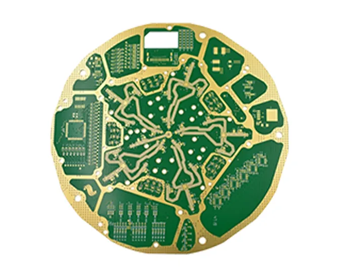
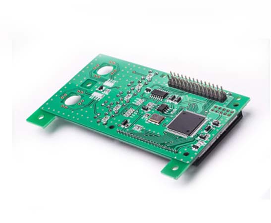
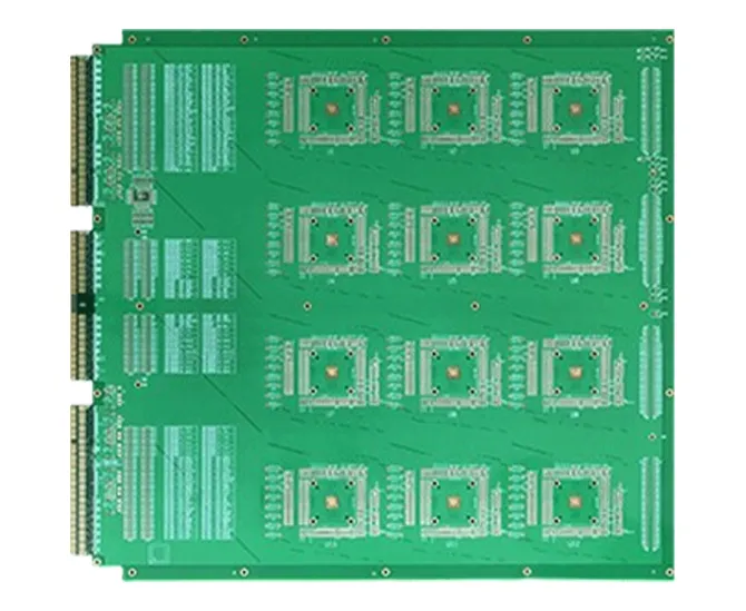
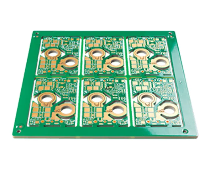
What Is an HDI PCB?
An HDI PCB board uses high-density interconnect technology to fit more electrical connections into a limited area. Fine traces, small connection pads and microvias help route signals from closely spaced components to the layers where they are needed.
HDI printed circuit boards are useful when conventional through-hole routing leaves too little room for component escape routing. HDI PCB technology can also shorten selected interconnections, while signal performance still depends on materials, reference planes, routing and the complete channel design.
We combine HDI fabrication with PCB assembly services for projects that need populated boards.
Does your board need HDI?
Start with component pitch, pin count, available board area and the required routing paths.
If a conventional multilayer PCB meets those requirements, extra build-up stages may add unnecessary cost. If routing is constrained, review the HDI stackup before completing the layout.
HDI PCB Fabrication Specifications
Use the following capabilities to start your project review. Share the actual layer connections, copper requirements and component pitch so we can confirm a manufacturable combination.
| Feature | Capability / option | What to specify |
|---|
| Trace width / spacing | Down to 50 / 50 µm
Approximately 2 / 2 mil | Minimum features by layer and copper weight; allow manufacturing margin where the layout permits. |
|---|
| Laser microvia diameter | Down to 0.10 mm | Via depth, start/end layers, capture pads and registration requirements. Diameter alone does not define the usable structure. |
|---|
| Layer count | Up to 16 layers; higher counts on review | Total layers, board thickness, material system and the number of build-up layers on each side. |
|---|
| Sequential build-up | Structures up to 3+N+3 | Complete stackup and via map. Stacked microvias, staggered microvias and the number of lamination stages need separate review. |
|---|
| Interconnections | Laser microvias; blind and buried vias | Identify each via type and its layer span in the drill data and fabrication drawing. |
|---|
| Via filling / via-in-pad | Resin plugging; via-in-pad options | Specify filling, capping and planarity requirements. Copper-filled microvia requirements need explicit process confirmation. |
|---|
| Controlled impedance | ±10% tolerance | Target impedance, single-ended or differential structures, reference layers and required verification records. |
|---|
| Acceptance requirements | IPC Class 2 / Class 3 project requirements | Agree the applicable standard, revision, class and inspection plan in the order documentation. |
|---|
| Minimum order | 1 piece | Prototype quantity and anticipated production demand; tooling and engineering costs may apply. |
|---|
Minimum line width, microvia diameter and maximum layer count are individual capability limits. They are not automatically available together in every construction.
Select the HDI Stackup Around the Routing Requirement
In common build-up notation, N represents the number of copper layers in the central conventional board section. The numbers on either side describe added build-up layers. The layer notation does not specify whether the microvias are stacked or staggered.
1+N+1One build-up layer per side
A starting option when one additional routing transition on each side provides sufficient component escape routing.
Review: the BGA fanout, target pads and available routing area before adding complexity.
2+N+2Two build-up layers per side
Adds routing options across more layers for layouts that cannot be completed with a simpler structure.
Review: via arrangement, registration, dielectric thickness and additional process stages.
3+N+3More demanding interconnection
For advanced HDI PCB projects where the component layout requires further build-up layers.
Review: the exact via interfaces, assembly heat exposure and the qualification plan for the proposed construction.
For example, a 1+4+1 construction has six copper layers. Two boards with the same total layer count can still need different fabrication routes because their via connections differ. See our sequential lamination PCB process for more on build-up manufacturing.
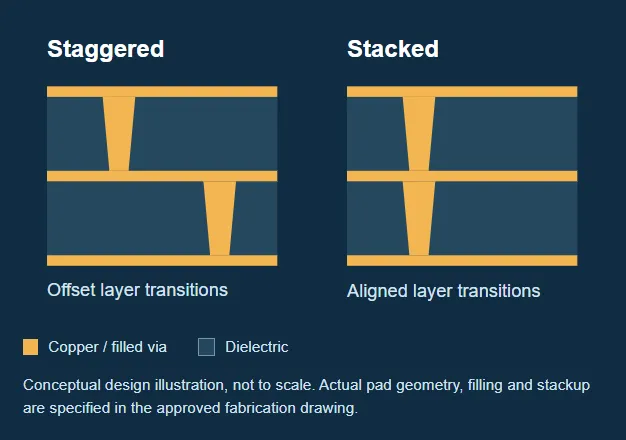
Stacked and staggered microvias
Staggered microvias are offset between successive dielectric layers and connect through an intermediate copper feature. They use more lateral space.
Stacked microvias align vertically. They conserve routing space but make the integrity of the filled via and its interfaces especially important.
We review the proposed arrangement with the build-up structure and reliability requirements. A 3+N+3 stackup does not automatically mean three vertically stacked microvias.
Explore microvia PCB technology, blind via PCB construction and buried via interconnections.
Our HDI PCB Fabrication Process
HDI technology in PCB manufacturing combines circuit patterning, layer bonding and precision interconnections. The sequence depends on the approved stackup and which connections must be formed at each stage.
01Engineering release
Review the manufacturing files, material system, build-up structure, via treatment and acceptance requirements. Resolve open questions before tooling.
02Core circuitry and inner-layer checks
Form the core circuitry and the specified internal connections. Check the features that will become inaccessible after lamination.
03Build-up lamination and laser drilling
Add the specified dielectric and copper layers. Form the laser microvias for the layer pairs in that build-up stage.
04Metallization and via treatment
Prepare and metallize the via surfaces, then apply the agreed filling or capping process where required. Repeat build-up operations for additional stages.
05Outer layers, solder mask and finish
Complete outer-layer features, solder-mask openings, pad finish and board profile against the released fabrication data.
06Inspection, testing and delivery
Complete the agreed inspections and electrical tests. Supply bare boards or continue into component assembly and its separate test plan.
Learn more about laser-drilled PCB manufacturing and BGA, QFN and fine-pitch PCB assembly.
Where HDI Circuit Boards Fit
Select HDI technology when component density, packaging or interconnect requirements justify the construction. Qualification requirements depend on the finished product and its operating environment.
Wearables and connected devices
Compact sensing and communication modules that need coordinated component placement and interconnections.
IoT and edge-device assemblyMedical equipment
Space-constrained monitoring and diagnostic electronics with clearly defined material, traceability and validation requirements.
Medical PCB project requirementsHigh-speed networking
High-pin-count devices and dense signal routing, with impedance, loss and return-path requirements assessed together.
High-speed PCB manufacturingAerospace control modules
Compact electronic assemblies where the interconnect structure needs an application-specific acceptance and qualification plan.
Aerospace PCB requirements
HDI PCB Cost, Lead Time and MOQ
HDI PCB cost depends on more than finished board size. Build-up stages, material utilization, microvia construction and acceptance requirements all affect the manufacturing route.
Stackup complexity: Layer count, lamination stages, material system and finished thickness.
Via and fine-line features: Layer-pair connections, stacked or staggered arrangements, via-in-pad treatment and feature density.
Quantity and panel use: Order quantity, tooling, board outline, panel utilization and planned repeat orders.
Testing and delivery: Inspection records, qualification work, assembly scope and requested schedule.
To compare quotes, use the same drawing revision, stackup, via treatment, finish, quantity and inspection scope. Ask for tooling, bare-board fabrication, assembly and delivery charges to be identified separately.
From the first board to repeat production
These are planning estimates. Your quotation confirms the production schedule and delivery date after file approval, material availability and testing requirements are reviewed. Transit time is quoted separately.
For an urgent build, send complete files and the required delivery date so we can assess an expedited schedule.
Technical Capabilities & Certifications
• Min Trace/Space: 50/50μm
• Laser-drilled Microvias: ≤ 0.1mm
• Layer Count: Up to 16+
• Via Filling: Resin Plugging
• Impedance Control ±10%
• IPC Class 2 & 3 compliance
• ISO 9001, ISO 13485, UL certified
These advanced HDI features are made possible by our specialized PCB manufacturing capabilities, ensuring precision and reliability for compact, high-speed designs.
Customer Testimonials
“China 365PCB’s HDI boards exceeded our expectations—flawless microvias and exceptional impedance control.” — Lukas T., Switzerland
“We rely on their HDI production for our aerospace-grade modules. They never disappoint.” — David M., USA
FAQ
Q1: Can you manufacture HDI PCBs with 3+ sequential buildup layers?
A1: Yes, we support HDI PCBs up to 3+N+3 structures with sequential lamination.
Q2: What is the minimum laser via size in your HDI circuit boards?
A2: We offer microvias down to 0.1mm in diameter, suitable for compact electronics.
Q3: Are HDI boards suitable for RF or high-speed digital applications?
A3: Absolutely. HDI PCB’s controlled impedance and short interconnects reduce signal loss.
Q4: Do you provide HDI PCBs with via-in-pad design?
A4: Yes, our advanced via-filling techniques support via-in-pad HDI structures.
Q5: Can I get quick-turn HDI PCB prototypes?
A5: Yes, our express service delivers HDI prototypes in as fast as 5 working days.
 English