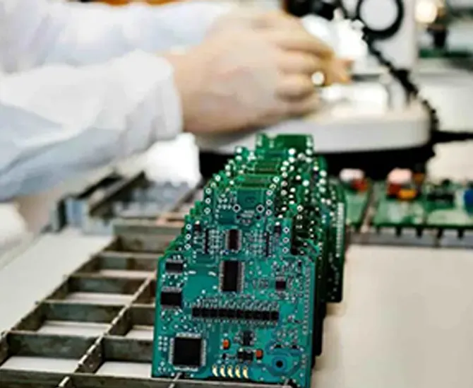
Start With the Board Architecture
Before placement begins, define:
Mechanical Envelope
Connector Locations
Board Outline
Mounting Holes
Major Functional Areas
Power Entry
High-Speed Interfaces
RF / Antenna Region
Analog Region
Processor / FPGA
Memory
Power Conversion
Thermal Paths
Layout Begins With Architecture — Not Routing.
Understand the Product Before the PCB
The PCB exists inside a product.
Therefore layout must understand:
Enclosure
Display
Battery
Cables
Heatsink
Fans
Sensors
Antenna
Mechanical Fixtures
External Connectors
The PCB Is One Mechanical and Electromagnetic Layer of the Product.
Mechanical Constraint Definition
Important constraints may include:
Board Dimensions
Component Height
Keep-Out
Connector Position
Screw Locations
Edge Clearance
Enclosure Ribs
Heatsinks
Thermal Interfaces
A Perfect Electrical Layout That Does Not Fit the Product Is Not a Valid Layout.
ECAD / MCAD Coordination
Electrical and mechanical design should increasingly operate together.
A useful workflow is:
↕
↕
before routing becomes deeply committed.
Electrical Placement and Mechanical Design Should Converge Together.
Functional Partitioning
Group circuits according to function.
For example:
Processor
Memory
Power
Analog
RF
Sensors
External Interfaces
But functional grouping is only the beginning.
The deeper question is:
Which Circuits Can Electromagnetically Affect Each Other?
Aggressor and Victim Analysis
Potential aggressors include:
Switching Regulators
DDR
SerDes
Clocks
Motor Drivers
High-Current Switching
Potential victims include:
ADC
PLL
Oscillator
GNSS
Low-Level Sensors
RF Receivers
Placement Is Electromagnetic Risk Management.
Energy-Based Placement
Instead of asking only:
Which components belong together?
also ask:
Where is electrical energy changing fastest?
High:
dv/dt
and
di/dt
regions deserve special attention.
Place According to Energy Flow — Not Only Functional Labels.
Signal-Flow Placement
A useful principle for many circuits is:
For example:
or:
Good Placement Makes the Electrical Path Obvious.
Critical Placement Before General Placement
Place first:
CPU / FPGA
Memory
Clock
Power Regulators
RF Devices
Connectors
Critical Analog
then secondary components.
Place Components in the Order of Constraint Severity.
PCB Stack-Up Engineering
The PCB stack-up determines:
Signal Layer Positions
Reference Planes
Dielectric Thickness
Copper Thickness
Impedance
Coupling
Routing Density
Power Distribution
Stack-Up Is Electrical Architecture in the Z-Axis.
Stack-Up Before Routing
A common mistake is:
Route first and ask the manufacturer for stack-up later.
For demanding boards:
Stack-Up Should Be Defined Before Critical Routing.
Because trace geometry depends directly on:
dielectric thickness
copper thickness
reference structure
Reference Plane Assignment
Each high-speed signal layer should have an intentional reference plane.
A possible structure:
but the correct architecture is product-specific.
Every Fast Signal Needs a Defined Return Environment.
Signal-to-Reference Spacing
The electric and magnetic fields around a PCB trace depend strongly on distance to its reference plane.
Closer reference spacing can:
strengthen field confinement
reduce loop area
affect impedance
The Reference Plane Is Part of the Transmission Line.
Microstrip
A surface trace referenced primarily to a plane beneath it behaves as a microstrip-like structure.
Its fields exist partly:
inside dielectric
and partly:
outside the PCB.
This can influence:
effective Dk
radiation
loss
Stripline
An internal signal trace between reference planes provides stronger field confinement.
Potential advantages can include:
reduced radiation
more homogeneous dielectric environment
Trade-offs can include:
additional via transitions
dielectric loss
Layer Choice Changes Channel Physics.
Coplanar Structures
Grounded coplanar structures can be useful in:
microwave
selected high-speed applications
But side-ground geometry changes:
impedance
and
field distribution.
Nearby Ground Is Part of the Transmission-Line Geometry.
Controlled Impedance
A controlled-impedance trace is determined by:
Therefore:
Differential Impedance
Differential impedance depends on:
individual trace geometry
pair spacing
reference plane
dielectric
But the pair also has:
odd-mode
even-mode
and
common-mode
behavior.
Differential Routing Is an Electromagnetic Structure — Not Two Ordinary Traces.
Stack-Up Manufacturability
The theoretically ideal stack-up may not be the most manufacturable.
It should be coordinated with:
available laminate
prepreg
copper
drilling
lamination
impedance tolerance
IPC explicitly emphasizes communication between designers and experienced fabricators for specialized high-frequency structures to ensure design intent is manufacturable.
Design the Electrical Stack-Up With the Fabrication Process in Mind.
Layer Count Optimization
More layers can provide:
routing space
cleaner reference planes
better power distribution
but increase:
fabrication complexity
The objective is not:
Minimum Layer Count.
It is:
Minimum Practical Layer Count That Preserves Electrical and Manufacturing Margin.
Symmetric Stack-Up
Mechanical balance can be influenced by:
dielectric structure
copper distribution
layer symmetry
This can affect:
warpage
and
manufacturing stability.
Electrical Stack-Up Is Also Mechanical Stack-Up.
Copper Balance
Large asymmetry in copper distribution can affect fabrication behavior.
Therefore layout should consider not only:
Where do we need copper electrically?
but:
What manufacturing structure are we creating?
Copper Has Mechanical Consequences Too.
Component Placement
Placement determines:
routing length
return path
coupling
thermal interaction
testability
assembly
Good Routing Begins With Good Placement.
Many routing problems are actually placement problems discovered too late.
Placement by Connectivity
Highly connected components should often be positioned to reduce unnecessary path length.
Examples:
CPU ↔ DDR
FPGA ↔ SERDES Connector
RF IC ↔ Antenna
Connectivity Density Should Influence Physical Distance.
Placement by Timing
A critical synchronous interface may need:
short propagation
controlled skew
Therefore physical distance can be part of the timing budget.
Placement Can Consume Timing Margin Before Routing Begins.
Placement by Power
High-current loads should be considered relative to:
regulators
power planes
decoupling
Don't Force Hundreds of Amps of Transient Current to Travel Across the Board Because Placement Looked Neater.
For ordinary lower-current products the same principle still applies proportionally.
Placement by Thermal Flow
Heat-generating components should consider:
airflow
heatsink
board edge
thermal spreading
Electrical Placement Can Create or Solve Thermal Problems.
Placement by EMC
Separate sensitive circuits from strong switching fields where architecture permits.
For example:
should not be casually placed beside:
high-current switching node.
Distance Is One Form of Electromagnetic Filtering.
Placement by Manufacturing
Assembly requires:
component clearance
placement access
rework feasibility
Extremely dense placement may be electrically attractive but hard to assemble reliably.
Density Has a Manufacturing Cost.
BGA Placement
Large BGA devices often become the center of the PCB routing architecture.
They influence:
Layer Count
HDI
Via Strategy
Memory Placement
Power Distribution
A Large BGA Is Not Just a Component.
It Is a Routing Topology.
BGA Escape Planning
Before routing, determine:
Ball Pitch
Pad Size
Via Type
Number of Rows
Escape Channels
Layer Allocation
BGA Escape Should Be Planned Before the First Trace Leaves the Package.
Dog-Bone Escape
Traditional dog-bone fanout can work well when pitch permits.
But tighter pitch increasingly reduces space for:
trace
pad
via
between balls.
Package Pitch Can Determine PCB Technology.
Via-in-Pad
Via-in-pad can provide direct vertical escape from component pads.
Potential benefits include:
routing density
reduced stub
improved placement freedom
But it requires appropriate fabrication processes.
Via-in-Pad Is Both a PCB Design Feature and a Fabrication Process Decision.
Filled / Capped Via Requirements
When vias exist in component lands, fabrication may require controlled filling and surface treatment to support reliable assembly.
Layout Features Have Manufacturing Process Consequences.
HDI
HDI can use:
Microvias
Blind Vias
Buried Vias
Sequential Lamination
to increase routing density.
But HDI should not be added simply because:
it sounds advanced.
Use HDI When It Solves Density, Electrical or Packaging Constraints.
Sequential Lamination
Complex HDI structures may require several lamination stages.
Each stage adds:
cost
process complexity
registration requirements
Every Additional HDI Build Step Should Create Real Design Value.
Microvia Architecture
Possible structures include:
or
microvias.
The appropriate architecture depends on:
routing
reliability
fabrication capability
Microvia Geometry Is Reliability Geometry.
Stacked Microvias
Stacked structures can provide high-density vertical connectivity.
But they also increase dependence on:
plating
interface quality
lamination
process control
Density and Reliability Must Be Engineered Together.
Staggered Microvias
Staggering can change:
routing area
layer transition
reliability behavior
The decision should be made with the fabricator according to project requirements.
Through Vias
Conventional plated through vias remain extremely valuable.
Advanced design does not mean eliminating older technologies.
Use the Simplest Via Structure That Meets the Electrical and Density Requirements.
Via Geometry
A via contains:
Barrel
Pad
Antipad
Stub
Reference Transition
Each contributes to high-frequency behavior.
A Via Is a Three-Dimensional Electrical Structure.
Signal Via Inductance
Vias introduce inductive behavior.
That becomes increasingly important as signal edge rate rises.
But via inductance cannot be understood independently of:
Return Path.
Via Capacitance
Pads and antipads create capacitive loading.
Changing:
antipad size
can materially alter local via impedance.
Via Optimization Is an L-C Geometry Problem.
Via Stub
If a signal transitions only part of the PCB thickness, unused via barrel can remain.
That stub can behave as:
A Resonant Structure.
At sufficiently high frequency it can strongly affect insertion and return loss.
Back Drilling
Back drilling removes unused via barrel.
It can reduce:
stub resonance
channel discontinuity
and can become highly valuable for demanding SerDes channels.
Remove Copper the Signal Does Not Need When That Copper Becomes an Electrical Problem.
Back-Drill Depth Control
Back drilling introduces manufacturing tolerance.
The designer should understand:
residual stub
drill tolerance
layer structure
Back Drilling Is a Manufactured Electrical Parameter.
Blind Via for High-Speed Channels
A blind via can avoid long unused through-hole stubs.
But the electrical benefit should be weighed against:
cost
reliability
Optimize the Complete Product — Not One Via.
Return Vias
When a high-speed signal changes layers and reference environment, the return current needs a nearby path.
Ground vias can support that transition.
Every Signal-Layer Transition Is Also a Return-Path Transition.
Return-Path Continuity
One of the most important PCB principles is:
Signals Travel in Loops.
Not merely along traces.
A signal path is:
Return Current.
If the return path is interrupted, the current finds another route.
Return Current at High Frequency
At high frequencies, return current tends to concentrate near the signal path because this minimizes electromagnetic loop inductance.
The Return Current Follows Field Geometry — Not the Shortest DC Resistance Path Alone.
Plane Splits
Routing a fast signal across a split in its reference plane can force return current to take a longer path.
Consequences can include:
larger loop area
impedance discontinuity
radiation
crosstalk
Never Cross a Reference-Plane Gap Without Understanding the Return Path.
Ground as a Reference Plane
A continuous ground reference is extremely valuable for many high-speed systems.
But the deeper rule is:
Preserve Return-Current Continuity.
not:
Ground plane solves everything automatically.
Power Plane as Signal Reference
A signal can sometimes reference a power plane.
But when transitioning between different reference planes, return-current continuity still needs consideration.
Reference-Plane Changes Need an AC Return Path.
Stitching Capacitors
Where a signal's return transitions appropriately between power/ground reference structures, capacitor placement can sometimes support AC return continuity.
The decision should follow the actual PDN/stack-up design.
Return Paths Should Be Engineered — Not Patched After EMC Failure.
Loop Area
Radiation and inductive behavior are strongly influenced by loop area.
Therefore:
Minimize the Area Between Forward and Return Current.
This principle applies to:
digital signals
power switching
clocks
analog
Clock Routing
Clocks often have:
high activity
continuous switching
and therefore significant EMI potential.
They should be routed with strong attention to:
reference
topology
length
isolation
A Clock Is an Aggressor That Never Gets Tired.
Oscillator Placement
Crystal and oscillator structures should generally remain close to the relevant device according to platform requirements.
Avoid unnecessary loops.
Time-Critical Analog Oscillation Should Not Tour the PCB.
High-Speed Digital Routing
Modern digital routing should be based on:
Edge Rate.
Not merely clock frequency.
A nominally “100 MHz” signal with extremely fast edges can behave as a high-frequency transmission-line problem.
Fast Edges Create High-Frequency PCB Physics.
Transmission-Line Threshold
Whether a trace should be treated as a transmission line depends on:
signal transition time
relative to:
propagation delay.
Frequency Label Alone Does Not Define High Speed.
High-Speed Topology
A signal may use:
Point-to-Point
Daisy Chain
Fly-By
Multi-Drop
depending on protocol.
The topology strongly influences reflections.
Topology Is Part of Signal Integrity.
Point-to-Point
Many SerDes links use point-to-point channels.
The layout objective is to create a controlled path from:
to:
with manageable:
loss
reflections
crosstalk
Multi-Drop
Parallel buses can connect multiple loads.
Stubs and branch points can create reflections.
Every Branch Creates an Electrical Decision.
Fly-By Routing
Memory interfaces such as certain DDR architectures may use fly-by command/address topology.
This intentionally creates propagation differences that are then handled through training/timing architecture.
Not All Signals Should Arrive Simultaneously by Geometry Alone.
Protocol matters.
Length Matching
Length matching should follow:
Timing Requirements.
Not cosmetic symmetry.
Two nets with identical physical length may not have identical electrical delay if their geometries or layer environments differ.
Match Delay — Not Just Millimeters.
Electrical Length
Propagation delay depends on:
dielectric environment
routing layer
geometry
Therefore one inch of microstrip may not have exactly the same delay as one inch of stripline.
Physical Length and Electrical Length Are Not Always the Same Thing.
Serpentine Routing
Meanders can add delay.
But overly dense serpentine geometry can create self-coupling.
A Meander Is a Coupled Transmission Structure — Not Free Length.
Serpentine Spacing
Tightly spaced meanders can partially cancel the delay engineers expect to add because fields couple between adjacent segments.
Length Matching Can Defeat Itself if the Geometry Is Poor.
Differential-Pair Routing
Differential pairs require control of:
pair spacing
reference
symmetry
skew
But perfect geometric coupling is not always the only objective.
The actual protocol/channel must guide design.
Intra-Pair Skew
Difference in propagation delay between:
and
can convert differential energy into common mode.
Differential Skew Can Become EMI.
Glass-Weave Effects
At very high speeds, dielectric glass/resin structure can contribute to differential delay variation.
Mitigation can involve:
routing angle
material architecture
trace geometry
depending on design.
Microscopic Material Structure Can Become Picosecond Timing.
Pair-to-Pair Skew
Parallel multi-lane protocols may also have requirements around lane alignment.
But modern interfaces can include:
training
deskew
so constraints should come from protocol specifications rather than generic rules.
Differential Pair Phase Matching
The relevant requirement is timing/alignment of the pair's electromagnetic mode.
Pretty Parallel Lines Are Not the Objective.
Stable Differential Signaling Is.
Pair Separation
Routing many pairs close together can increase crosstalk.
Spacing should be driven by:
edge rate
layer
geometry
acceptable coupling
Spacing Rules Should Come From Crosstalk Requirements.
Crosstalk
Coupling occurs through:
and
Magnetic Fields.
It depends on:
spacing
parallel length
reference
layer structure
Crosstalk Is Geometry Talking Between Nets.
Near-End and Far-End Crosstalk
Different transmission structures can exhibit different:
and
behavior.
This is why sophisticated high-speed routing may need field-solver/channel analysis rather than a universal “3W rule.”
Simple Spacing Rules Are Heuristics — Not Physics Limits.
Victim / Aggressor Classification
Not all crosstalk is equally dangerous.
A clock into an analog measurement can be more problematic than coupling between two unrelated slow control signals.
Route According to Consequence.
Orthogonal Routing
Routing adjacent signal layers in different directions can sometimes reduce long parallel coupling.
But reference planes and stack-up remain more fundamental.
Layer Assignment Should Be Electromagnetically Intentional.
SerDes Channel Design
Modern high-speed serial channels can include:
The PCB Is One Segment of the Channel Budget.
PCIe 7.0 Context
PCIe 7.0 officially doubled data rate to:
128 GT/s
in the 1.0 specification released in June 2025.
At this level, PCB layout must treat:
via structure
loss
return loss
crosstalk
reference discontinuity
as explicit channel-budget consumers.
At 128 GT/s, “It Looks Short” Is Not a Signal-Integrity Argument.
CXL 4.0 Context
CXL 4.0 likewise uses a 128 GT/s physical-link generation based on PCIe 7.0, while supporting advanced memory/connectivity architectures.
This reinforces the broader industry direction:
Compute Architecture Is Increasingly Limited by Interconnect Quality.
PAM4
Very high-speed interfaces increasingly use multi-level signaling such as PAM4.
Compared with binary NRZ:
vertical eye margin becomes smaller.
More Bits per Symbol Means Less Voltage Margin per Eye.
This makes noise, reflection and crosstalk more consequential.
Channel Loss
PCB traces have frequency-dependent loss from:
Conductor
Dielectric
Surface Effects
Discontinuities.
Channel Loss Is Not One Number Across Frequency.
Insertion Loss
Insertion loss quantifies how much signal energy is transmitted through a channel as frequency changes.
For high-speed systems:
Loss Budget Is a Design Resource.
Every:
trace
via
connector
consumes part of it.
Return Loss
Return loss describes reflected energy caused by impedance discontinuities.
A channel can have manageable insertion loss and still fail because of poor reflection behavior.
Loss and Reflection Are Different Problems.
S-Parameters
A complex channel can be represented using:
S-Parameters.
These enable analysis of:
transmission
reflection
crosstalk
across frequency.
High-Speed PCB Verification Often Moves From “Trace Length” to “Channel Network.”
Eye Diagram
Time-domain channel behavior can be evaluated through eye diagrams.
Important characteristics can include:
Eye Height
Eye Width
Jitter
Noise.
The Eye Is Where Multiple PCB Impairments Become One Communications Margin.
Equalization
Modern receivers/transmitters may provide:
pre-emphasis
de-emphasis
But:
Equalization Is Not Permission to Build a Poor Channel.
It can compensate only certain channel impairments.
Retimers
At very high data rates, long channels may use retimers.
CXL 4.0, for example, increased supported retimer architecture for extended channel reach.
But adding active channel elements creates:
cost
power
latency
thermal complexity
The Best PCB Channel Is Still the One That Preserves Margin Before Active Recovery Is Needed.
DDR Layout
DDR design is a coordinated system involving:
Controller
Package
PCB
DRAM
Termination
Power
Reference.
DDR Is Timing + SI + PI Co-Design.
DDR Data Byte Lanes
DQ signals are grouped with their DQS strobe.
Layout should preserve the intended byte-lane structure.
Route Memory According to Timing Groups — Not Alphabetical Net Names.
DQS Relationship
The important relationship is not:
Every DDR trace has exactly the same length.
It is:
Required Timing Relationships Are Maintained.
The exact constraints depend on memory generation/controller/vendor.
DDR Address / Command
Command/address structures can follow protocol-specific topologies and timing relationships.
Do Not Apply DQ Rules Blindly to CA Nets.
DDR Clock
Differential memory clocks deserve:
controlled impedance
return path
timing consideration
but all constraints should trace to:
platform timing model.
DDR Power Integrity
Memory switching activity can create substantial transient demand.
Important rails may include:
core
reference
A Perfect DDR Routing Topology Can Still Fail With Poor PDN Design.
VREF
Reference voltages should be treated as analog-sensitive nodes.
Digital Memory Uses Analog Thresholds.
Protecting references can directly protect timing margin.
Processor / FPGA BGA Escape
The escape architecture should coordinate:
Power Balls
Ground Balls
DDR
SerDes
GPIO
Clocks.
BGA Escape Is Resource Allocation Across Layers.
SerDes Ball-to-Via Geometry
The channel begins inside the package.
PCB fanout immediately adds:
pad
breakout trace
via
The First Few Millimeters Can Contain Several Discontinuities.
Breakout Routing
Fanout regions often require temporary narrower traces because of package geometry.
Those geometries should be minimized and understood.
A Short Impedance Discontinuity Is Still a Discontinuity.
Neckdowns
Neckdowns can be unavoidable.
The question is not:
Are neckdowns prohibited?
but:
Does this geometry consume acceptable channel margin?
High-Speed Design Is Margin Engineering — Not Rule Worship.
100 — Connector Launches
Transitioning between PCB and connector can create major impedance discontinuity.
Variables include:
pads
ground pins
antipads
via geometry
A High-Speed Connector Is Only as Good as Its PCB Launch.
101 — Edge Connectors
Card-edge structures can be part of:
backplane
module
interfaces.
The transition should be treated as part of the channel.
102 — High-Speed Cable Connectors
External high-speed connectors add:
footprint
launch
connector
cable
to the electrical budget.
Connector Selection Is Channel Selection.
103 — RF PCB Layout
RF PCB layout takes the principle:
even further.
At RF/microwave frequencies:
trace length
bend
pad
via
ground gap
can become intentional circuit parameters.
IPC-2228 explicitly treats RF transmission lines and associated structures as distributed circuits rather than ordinary lumped interconnections.
104 — RF Feedline
An RF path should preserve:
impedance
ground continuity
physical isolation
from device to:
antenna
or:
connector.
RF Routing Is Field Routing.
105 — RF Bend Geometry
At sufficiently high frequency, bends can create local discontinuity.
The correct mitigation depends on:
width
frequency
topology
Tiny Geometric Details Become More Important as Wavelength Shrinks.
106 — Ground-Via Fences
Ground vias can help:
contain fields
connect reference structures
isolate regions
especially in RF architecture.
But spacing should be based on electromagnetic behavior.
Via Fences Are Functional Structures — Not Decorative Dots.
107 — RF Isolation
Separate:
from:
and:
from sensitive receive paths
according to system architecture.
In RF Layout, Millimeters Can Be Isolation.
108 — Antenna Region
Antenna layout must coordinate:
feed
matching
ground plane
keep-out
mechanics.
The PCB Around the Antenna Is Part of the Antenna.
109 — Analog PCB Layout
Precision analog layout should preserve:
signal flow
reference
low noise
symmetry
Analog Layout Is About Preventing Unwanted Voltage From Becoming Part of the Measurement.
110 — Low-Level Signals
Microvolt/millivolt-class signals may be sensitive to:
ground drop
thermal gradients
digital switching
leakage
Small Signals Require Large Attention to Geometry.
111 — Differential Analog
Differential signal paths should maintain:
symmetry
similar parasitics
common environment
Common-Mode Rejection Can Be Destroyed by PCB Asymmetry.
112 — Kelvin Connections
Precision current or voltage measurement may require separate sensing paths.
Measure the Component Terminals — Not the Power Trace.
113 — Guarding
High-impedance analog circuits can use controlled guard structures where appropriate.
The design depends strongly on actual circuit and leakage requirements.
At High Impedance, PCB Surface Leakage Can Become a Circuit Element.
114 — Analog / Digital Boundary
A mixed-signal board should understand:
Where the signal changes from analog information to digital data.
This often informs:
return paths
power domains
115 — Ground Splitting Myths
Simply cutting the ground plane into:
and
can sometimes create worse return-path problems.
The correct question is:
Which Currents Are We Trying to Keep Apart?
Not:
How many ground names should we create?
116 — Continuous Ground Strategy
In many mixed-signal systems, a continuous ground plane combined with intelligent placement and current-path control can be more effective than arbitrary plane splits.
But each architecture must be evaluated individually.
Current Paths Matter More Than Labels.
117 — Power Supply Layout
Switching regulators have critical:
hot loops
switch nodes
feedback paths.
Power Layout Is Part of the Converter Circuit.
118 — Input Capacitor Placement
The input capacitor should support the high-frequency switching-current loop.
Millimeters of Extra Power Loop Can Create Nanohenries of Unwanted Inductance.
119 — Switch-Node Geometry
The switch node combines:
high dv/dt
with significant electrical energy.
Excessive copper can increase capacitive coupling.
Don't Make the Strongest Noise Source Larger Than Necessary.
120 — Feedback Routing
Feedback should sense the intended output point while avoiding switching noise.
A Regulator Controls What Its Feedback Pin Believes.
121 — Power Copper
High-current rails need:
adequate width
thickness
via capacity
thermal evaluation
IPC's current DFM framework combines requirements from multiple design/performance standards when evaluating board manufacturability, reinforcing that current, geometry, fabrication and assembly cannot be treated separately.
122 — Current Density
A narrow bottleneck can dominate the resistance of an otherwise wide plane.
Current Path Capacity Is Determined by the Weakest Geometry Along the Path.
123 — Via Arrays for Current
Moving high current between layers may require multiple vias.
But effective current distribution depends on geometry.
Ten Vias Are Useful Only If Current Can Actually Reach All Ten.
124 — Power Distribution Network — PDN
The PCB power system is a network:
Die.
Power Integrity Is a PCB Layout Discipline.
125 — Target Impedance
A target-impedance approach relates:
to:
Transient Current.
High-current low-voltage rails can require extremely low PDN impedance.
Voltage Margin Determines Impedance Budget.
126 — Decoupling Placement
Capacitor effectiveness depends on:
capacitance
mounting geometry
The Same Capacitor Can Behave Differently Depending on Where and How It Is Mounted.
127 — Mounting Inductance
A capacitor with long traces/vias may have significantly worse high-frequency behavior than one connected compactly.
PCB Geometry Is Part of the Capacitor.
128 — Via-to-Capacitor Geometry
Power/ground via position around decoupling capacitors can influence loop inductance.
Decoupling Is a Two-Terminal Current Loop, Not a Component Placement Ritual.
129 — BGA Decoupling
Large processors may need capacitors:
beneath
or very close to the package,
depending on mechanical/assembly constraints.
Distance to Silicon Matters at High Frequency.
130 — Plane Capacitance
Closely spaced power/ground planes contribute distributed capacitance.
This can be valuable at frequencies where discrete capacitors are increasingly limited by mounting inductance.
The PCB Stack-Up Can Become Part of the Decoupling Network.
131 — PDN Resonances
Capacitors, planes and inductance form resonant structures.
Some combinations can create:
anti-resonance peaks.
More Capacitors Does Not Automatically Mean Lower Impedance Everywhere.
132 — PI Simulation
High-performance platforms can use power-integrity simulation to evaluate:
impedance
current density
voltage drop
resonance
before hardware.
Simulate the PDN Where Power Margin Is Expensive.
133 — DC IR Drop
Power planes have finite resistance.
A high-current processor can experience voltage loss between:
and
load.
A 1.0 V Rail Cannot Afford the Same Absolute Voltage Drop as a 12 V Rail.
134 — Remote Sense
Where supported, regulator sense points may compensate PCB voltage drop.
But sensing paths must be carefully routed.
Regulate Where Voltage Matters.
135 — Ground Bounce
Shared inductance in ground paths can create transient reference movement.
Ground Is Not Zero Volts Everywhere at Every Frequency.
This is one of the most important concepts in high-performance layout.
136 — Simultaneous Switching Noise
Large FPGA/processor I/O groups switching simultaneously can stress the PDN and reference network.
Signal Integrity Can Become Power Integrity.
137 — SI / PI Co-Design
Poor PDN causes:
jitter
threshold modulation
while poor signal return can disturb:
ground
reference
SI and PI Are Two Views of the Same Electromagnetic System.
138 — EMC-Aware Layout
EMC should not begin after routing is complete.
Key layout controls include:
Loop Area
Return Paths
Clock Geometry
Switching Nodes
Connector Boundaries
Cable Currents
EMC Is Often a PCB Current-Path Problem.
139 — Common-Mode Conversion
Perfect differential signals ideally create limited common-mode energy.
Asymmetry can convert:
Common-mode current is often far more effective at driving cables and radiation.
Control Symmetry to Control Radiation.
140 — PCB-to-Cable Transition
Cables can become efficient antennas.
The PCB should avoid driving unwanted common-mode energy onto them.
Connector Ground Architecture Can Determine System EMC.
141 — Chassis Ground
Some products have:
signal ground
and
chassis.
Their relationship should be deliberately engineered according to EMC/safety architecture.
Chassis Is an Electromagnetic Structure — Not Just Mechanical Metal.
142 — Shield Connections
Cable shields should terminate according to the interface and EMC design.
Long “pigtail” ground paths can behave poorly at high frequency.
Shield Effectiveness Depends on High-Frequency Current Path.
143 — ESD Layout
ESD protection should intercept transient current before it travels through sensitive circuitry.
A conceptual path is:
Protection Component Placement Determines Where the ESD Current Flows.
144 — TVS Placement
A TVS located far from the connector can allow transient energy to travel through more PCB structure before clamping.
Protection Should Be Physically Close to the Threat Boundary Where Architecture Requires It.
145 — Surge Current Path
High-energy transients need low-impedance current paths to their intended destination.
Don't Let Protection Current Choose Its Own Route Through the PCB.
146 — Isolation Layout
Isolation design involves:
Isolation Is Three-Dimensional Geometry.
147 — Isolation Keep-Out
Copper, vias and components must respect defined isolation boundaries.
A Hidden Internal-Layer Copper Pour Can Defeat a Beautiful Top-Layer Clearance.
148 — Creepage vs Clearance
They are different concepts.
Clearance relates to distance through air.
Creepage relates to distance along insulating surface.
Safety Geometry Must Be Evaluated According to the Applicable Product Standard.
149 — PCB Slots
Slots can alter creepage paths and isolation geometry.
But they also affect:
mechanical strength
fabrication
Safety Geometry Is Manufacturing Geometry.
150 — Thermal PCB Layout
Every power-dissipating component has a thermal path.
Possible paths include:
or:
PCB Layout Determines Where Heat Can Go.
151 — Thermal Vias
Thermal vias can transfer heat between layers.
Their usefulness depends on:
geometry
copper
destination plane
A Thermal Via Needs Somewhere Cooler to Deliver the Heat.
152 — Thermal Spreading
Large copper regions can distribute heat away from a source.
But this may conflict with:
isolation
current paths
Thermal and Electrical Optimization Share the Same Copper.
153 — Hotspot Interaction
Placing:
high-current inductor
all together can create a concentrated thermal region.
Electrical Proximity Can Create Thermal Density.
154 — Temperature-Sensitive Components
Temperature-sensitive devices can include:
precision references
oscillators
sensors
They should be placed with thermal gradients in mind.
Heat Is a Noise Source for Precision Electronics.
155 — Thermal Gradient
Differential analog circuits can experience thermal-induced offset when components sit at different temperatures.
Symmetric Electrical Design Benefits From Symmetric Thermal Environment.
156 — Mechanical Stress
Board flex can affect:
solder joints
large BGA
ceramic capacitors
Placement should consider:
mounting points
connector force
enclosure flex
PCB Layout Is Also Structural Engineering.
157 — Large BGA Near Board Edge
Mechanical strain can be higher in certain board regions.
The final reliability decision should consider product mechanical environment.
158 — MLCC Placement
Large ceramic capacitors can be mechanically sensitive to board flex.
Component Reliability Depends on Where the PCB Bends.
159 — Connector Mechanical Load
Connectors can transfer insertion/removal forces into the PCB.
Mounting and nearby component placement should account for that.
160 — Flex PCB Layout
Flexible circuits require a different design philosophy from rigid PCB.
Important considerations include:
bend region
copper direction
neutral axis
stiffeners
transition zones
IPC's current board-design portfolio maintains dedicated flexible/rigid-flex design requirements separate from rigid-board design, reflecting these different mechanics.
A Flex PCB Is a Mechanical Structure Carrying Electrical Signals.
161 — Rigid-Flex
Rigid-flex combines:
with
Flexible Interconnect.
The transition region becomes especially important.
Rigid-Flex Design Must Coordinate Electrical, Mechanical and Lamination Architecture.
162 — Bend Regions
Avoid unnecessary stress concentration in active bend areas.
Layout decisions should follow:
bend direction
number of flex cycles
copper architecture
Flex Reliability Begins With Knowing How the Product Moves.
163 — RF + Flex
Flexible RF transmission lines introduce additional complexity from:
material
bending
reference geometry
Mechanical State Can Become RF State.
164 — Testability
PCB layout should reserve access for relevant:
power rails
programming
debugging
A PCB That Cannot Be Tested Is Difficult to Manufacture Reliably.
165 — Probe Access
Test pads need:
physical access
electrical validity
A pad hidden under another component may exist in CAD but not in manufacturing reality.
Test Access Must Be Physically Reachable.
166 — ICT Constraints
In-circuit test can influence:
pad size
spacing
fixture access
This should be considered before final routing.
DFT Must Influence PCB Geometry Before Release.
167 — Boundary Scan
Where JTAG/boundary scan is used, the PCB architecture should preserve:
chain connectivity
access
Digital Test Architecture Has Physical Layout Requirements Too.
168 — Programming Pads
High-volume products can use fixture-accessible programming pads rather than permanent headers.
Development Interface and Manufacturing Interface Can Be Different Physical Implementations.
169 — Fiducials
Assembly equipment may require:
board
local fiducials
according to component/process requirements.
Placement Accuracy Begins With Machine Registration.
170 — Panelization Inputs
Individual PCB layout can affect:
panel efficiency
tooling
depanelization
Board Shape Is Manufacturing Economics.
171 — Edge Clearance
Components/traces near board edges need appropriate manufacturing/mechanical margin.
The required value is process-specific.
PCB Edges Are Manufacturing Boundaries.
172 — Depanelization Stress
V-scoring, routing tabs or other panel-separation methods can introduce mechanical stress.
Sensitive components near separation areas deserve consideration.
Manufacturing Happens to the Board After Assembly Too.
173 — DFA — Design for Assembly
Layout should support:
placement
soldering
inspection
repair
IPC's current DFM framework explicitly treats DFM as a formal design-phase requirement rather than something to postpone until fabrication.
Layout Quality Includes Assembly Quality.
174 — Component Orientation
Consistent orientation where practical can help:
assembly
inspection
human review
but electrical performance remains primary.
175 — Fine-Pitch Components
Fine-pitch packages affect:
stencil
solder mask
assembly
inspection
PCB Layout and SMT Process Meet at the Land Pattern.
176 — BGA Assembly
BGA land/via architecture affects:
soldering
reliability
BGA Layout Is PCB Design + Assembly Process Design.
177 — QFN Thermal Pads
Large exposed pads can require:
via strategy
paste segmentation
in coordination with assembly engineering.
Thermal Electrical Pads Are Manufacturing Structures Too.
178 — DFM
DFM asks:
Can This Geometry Be Manufactured Repeatedly?
not merely:
Can one prototype be fabricated?
179 — Minimum Feature vs Production Feature
A manufacturer may technically support:
X µm trace/space.
But using that minimum everywhere can reduce:
yield
margin
supplier flexibility
Maximum Capability Is Not the Same as Recommended Production Geometry.
180 — Producibility Margin
A strong production design avoids unnecessary use of process limits.
Don't Spend Manufacturing Margin Where the Product Gets No Electrical Value From It.
181 — Design Rules by Net Class
Different networks deserve different rules.
For example:
General GPIO.
One Global Clearance Rule Cannot Represent Every Electrical Requirement.
182 — Constraint Management
Layout constraints can include:
Width
Spacing
Impedance
Length
Skew
Via Count
Layer
Return Requirements
Constraints Are the Machine-Readable Form of Engineering Intent.
183 — Constraint Traceability
Every unusual rule should ideally have an engineering reason.
For example:
should trace to the actual platform requirement, not inherited tribal knowledge.
A Rule Without a Reason Eventually Becomes a Mistake.
184 — Pre-Layout SI Simulation
Before routing, simulation can answer:
What topology?
Which termination?
Which layer?
What impedance?
Solve Architecture Questions Before Detailed Routing.
185 — Post-Layout SI Verification
After routing, actual geometry can be extracted and analyzed.
The model can include:
vias
bends
length
connector
Post-Layout Analysis Verifies What Was Actually Designed.
186 — 3D EM Extraction
Critical geometries such as:
connector launch
via field
may benefit from full-wave EM modeling.
When Geometry Becomes Too Complex for Simple Rules, Solve the Fields.
187 — Post-Layout PI
Actual:
plane shapes
via placements
capacitor positions
can be included in PDN analysis.
The Final PDN Is Geometry — So Verify the Final Geometry.
188 — Thermal Simulation
PCB/component geometry can feed thermal modeling.
This can identify:
hotspots
insufficient spreading
enclosure limitations
before tooling.
189 — EMC Prediction
While full EMC prediction remains difficult, field/current modeling and good return-path analysis can identify significant risks.
EMC Engineering Is Strongest When Prediction and Measurement Feed Each Other.
190 — Design Rule Checking — DRC
DRC verifies that layout satisfies encoded rules.
It can identify:
spacing
width
clearance
unconnected nets
But:
DRC Cannot Tell You Whether the Architecture Is Good.
191 — Zero-Unexplained-DRC Philosophy
Every violation should be:
fixed
or:
explicitly approved.
Waivers Should Be Engineering Decisions — Not Alert Fatigue.
192 — Connectivity Verification
Before release:
all nets routed
no unintended shorts
no forgotten stubs
“100% Routed” Does Not Mean “100% Correct.”
193 — Visual Engineering Review
Experienced human review can still identify:
strange geometry
unexpected return paths
routing inconsistencies
that rule checks may miss.
Automation Sees Rule Violations.
Engineers See Suspicious Intent.
194 — Cross-Probing
Schematic and PCB should remain tightly connected.
An engineer reviewing:
should be able to understand its:
schematic function
and
physical PCB path.
Logical and Physical Product Definitions Must Stay Synchronized.
195 — Revision Control
Every layout revision should be controlled.
A PCB change can affect:
electrical
thermal
mechanical
manufacturing behavior
Moving One Via Can Be a Product Change.
196 — ECO Impact Analysis
Examples:
PCB Changes Should Be Evaluated by Function — Not by Drawing Size.
197 — Gerber Is Not the Entire Product Definition
Gerber remains widely used, but complex production can benefit from richer design/manufacturing data.
IPC-2581C supports intelligent design-to-manufacturing information including advanced board features and bidirectional DFX communication.
Geometry Alone Does Not Communicate All Design Intent.
198 — IPC-2581 Digital Thread
IPC-2581C was developed specifically to improve digital data exchange from design through manufacturing and can carry far more structured product information than a traditional collection of independent manufacturing files.
The long-term direction should be:
Digital Product Definition Should Become a Closed Engineering Loop.
199 — ODB++ / Intelligent Data
Where appropriate to the customer's workflow, intelligent manufacturing packages can reduce manual interpretation.
The principle is:
Give Manufacturing Structured Information — Not a Puzzle of Independent Files.
200 — Fabrication Drawing
The PCB release should clearly define:
dimensions
stack-up requirements
material
finish
controlled impedance
special processes
The Fabrication Drawing Explains What Geometry Alone Cannot.
201 — Assembly Drawing
Assembly output should communicate:
component positions
polarity
variants
mechanical details
PCB Fabrication and PCB Assembly Are Different Product Definitions.
202 — Drill Data
Drill information should correctly distinguish:
plated
non-plated
blind
buried
back drill
and any special structures.
A Hole Is Not Just a Diameter.
It has:
electrical
and
process
meaning.
203 — Controlled-Impedance Coupons
Depending on project/fabricator, impedance coupons can support manufacturing verification.
Verify the Fabricated Transmission Structure — Not Only the CAD Calculation.
204 — High-Speed Test Coupons
Advanced products may use test structures for:
loss
material
impedance
via
characterization.
Measure the PCB Manufacturing Platform Where Channel Margin Matters.
205 — TDR Correlation
Time-domain reflectometry can identify impedance changes along a manufactured structure.
This allows:
vs.
comparison.
Measure the Structure the Factory Actually Built.
206 — S-Parameter Correlation
For demanding high-frequency/high-speed platforms, suitable test structures can provide frequency-domain characterization.
That should be a core 365PCB philosophy.
207 — Manufacturing-Tolerance Analysis
Actual PCBs vary.
Possible variables include:
Trace Width
Copper Thickness
Dielectric Thickness
Dk
Registration
Drill Position
Production Is a Distribution Around the CAD Model.
208 — Nominal vs Manufactured Geometry
The electromagnetic model should increasingly distinguish:
nominal design geometry
from:
real manufacturing geometry.
The Product Ships With Manufactured Dimensions — Not CAD Dimensions.
209 — Impedance Tolerance
A controlled-impedance target needs a manufacturing tolerance that reflects:
performance
material
process
Tight Tolerance Has Cost.
Use it where the electrical system needs it.
210 — Registration
Layer-to-layer registration can influence:
via lands
antipads
fine features
As geometries shrink:
Manufacturing Alignment Becomes Electrical Geometry.
211 — Etch Compensation
Fabrication modifies copper geometry.
The manufacturer may adjust artwork/process to achieve intended finished dimensions.
CAD Width Is Not Automatically Finished Copper Width.
212 — Copper Roughness
At high frequency, copper roughness can increase conductor loss.
Surface Texture Can Become Channel Loss.
This matters increasingly for long high-speed channels.
213 — Dielectric Material
Relevant properties can include:
Dk
Df
Temperature Behavior
Moisture
Glass Weave
Reliability
Material Selection Is Signal Integrity and Manufacturing Engineering Together.
214 — Dk Is Frequency- and Method-Dependent
A datasheet's Dk value should not automatically be treated as one universal electromagnetic constant across all geometries/frequencies.
Material Numbers Need Context.
215 — Loss Tangent / Df
Lower dielectric loss can improve high-frequency channel margin.
But material selection must consider:
as well.
Lowest Df Is Not Automatically Best Product Economics.
216 — Low-Loss Material Strategy
Use low-loss material when:
channel budget requires it.
Do not use expensive exotic laminate to compensate for avoidable:
routing length
bad vias
poor connectors
Fix Geometry Before Buying Margin From Material.
217 — Hybrid Material Stack-Ups
Some products combine:
with
conventional digital materials.
This can optimize cost/performance.
But mixed-material fabrication introduces:
lamination
process
considerations.
Material Optimization Can Move Complexity Into Manufacturing.
218 — Rigid Board Design Standards Context
IPC's current revision table lists:
IPC-2221C — Generic Standard on Printed Board Design
IPC-2222B — Rigid Organic Printed Boards
IPC-2223E — Flexible Printed Boards
IPC-2228 — High Frequency RF/Microwave Printed Boards.
For 365PCB, the important principle is not simply:
“Designed to IPC.”
It is:
Use the Applicable Standard Together With Product-Specific Electrical Requirements and Fabricator Process Capability.
219 — Rules Are Not Simulations
Standards provide extremely important generic requirements and best practices.
But they cannot know:
exact SerDes
exact stack-up
exact material
exact product
Standards Define Discipline.
Engineering Defines the Specific Design.
220 — PCB Layout Review Levels
A mature program can use several reviews.
Is the board physically organized correctly?
Are critical components in the right locations?
Are layer/reference structures appropriate?
Are channels physically correct?
Are current and PDN paths correct?
Are return paths and noise regions controlled?
Can the PCB be manufactured and assembled reliably?
Review Before the Design Becomes Expensive to Change.
221 — 30% Layout Review
Early review can catch:
board architecture
placement
layer strategy
before most routing is committed.
Correct Placement Early Is Cheaper Than Beautiful Rerouting Late.
222 — 60% Review
By mid-layout:
critical channels
power
routing strategy
should be increasingly visible.
The objective is to discover architectural conflicts before finishing.
223 — 90% Review
Near completion, verify:
constraints
return paths
testability
manufacturing
90% Review Should Not Be the First Time an SI Engineer Sees the Board.
224 — Final Release Review
Release should confirm consistency between:
Schematic
PCB
BOM
Fabrication Data
Assembly Data
Mechanical Data
Revision.
One Product Must Have One Release State.
225 — Prototype PCB Strategy
EVT boards can deliberately include:
measurement access
alternative values
optional routes
debugging
An EVT PCB Should Be Designed to Maximize Engineering Learning.
226 — Optional Components
Useful prototypes may preserve:
termination options
filter options
where uncertainty remains.
Controlled Flexibility Is Valuable During Learning.
227 — Debug Headers
Development boards may include generous:
test access
that production boards later optimize.
Prototype Layout and Production Layout Have Different Objectives.
228 — EVT Layout Validation
EVT should answer:
Does the PCB electrical architecture fundamentally work?
Evaluate:
power
clocks
memory
interfaces
analog
thermal
EVT Is Where Layout Physics Meets Real Hardware.
229 — DVT Layout
By DVT, layout should increasingly represent:
final mechanical
final components
final stack-up
final thermal architecture.
DVT Should Validate the Product — Not a Development Board.
230 — PVT Layout
PVT focuses on:
manufacturing repeatability
assembly
yield
test
PCB Layout Becomes a Manufacturing Specification at PVT.
231 — Production Feedback
Manufacturing can reveal:
registration issues
assembly yield
warpage
impedance trends
That data should feed back into design rules.
PCB Layout Should Learn From the Factory.
232 — Yield-Aware Layout
Suppose two layouts meet the same electrical requirement.
One operates close to:
fabrication limits.
The other leaves comfortable process margin.
The Second Can Be the Better Engineering Design Even if CAD Performance Looks Identical.
233 — Production Repeatability
The objective is not:
Build one perfect engineering sample.
It is:
Build Thousands of Boards Whose Physical Behavior Remains Inside the Required Electrical Envelope.
234 — Cost-Aware Layout
PCB cost can be influenced by:
layers
materials
via types
fabrication tolerances
Layout architecture therefore has significant economic impact.
PCB Cost Is Partly Determined Before the Manufacturer Quotes It.
235 — Value Engineering
Potential optimization may include:
reduce layers
simplify materials
improve panel utilization
but only if electrical/reliability performance remains protected.
Reduce Cost Without Reducing Required Margin.
236 — Over-Engineering
Too much:
exotic material
ultra-tight tolerance
layer count
can create unnecessary cost.
Advanced PCB Design Is Not Maximum Technology Everywhere.
It Is Correct Technology Where It Creates Value.
237 — AI-Assisted PCB Layout
AI and automation can increasingly support:
placement exploration
routing
constraint checking
But high-performance layout still requires understanding:
fields
return paths
timing
power
manufacturing.
AI Can Accelerate PCB Layout.
Engineering Must Still Own Electrical Sign-Off.
238 — Constraint-Driven Automation
The better the design rules, the more useful automation becomes.
Automation Cannot Protect Requirements That Were Never Captured.
This is why the previous:
page and this:
page are fundamentally connected.
239 — Digital Twin Direction
PCB geometry can become part of a broader digital representation containing:
Electrical
Mechanical
Thermal
Manufacturing
information.
IPC's current smart-factory/digital-product-data initiatives—including IPC-2581—are explicitly aimed at richer design-to-manufacturing information exchange.
Future PCB Design Is Increasingly Model-Based and Data-Connected.
240 — World-Class PCB Layout Design
At the highest level, the workflow is not:
It is:
That is the difference between:
and
Engineering the Physical Electrical System.
Depending on project complexity, a 365PCB ODM PCB-layout program may include:
PCB Architecture
Board Outline & Mechanical Inputs
ECAD / MCAD Coordination
Functional Partitioning
Placement Architecture
Aggressor / Victim Analysis
PCB Stack-Up Definition
Layer Assignment
Reference-Plane Architecture
Controlled-Impedance Requirements
Single-Ended Impedance
Differential Impedance
Material Recommendations
Layer-Count Optimization
BGA Escape Architecture
Via Technology Selection
Through-Via Design
Blind / Buried Via Design
Microvia / HDI Inputs
Via-in-Pad Design
Back-Drill Requirements
Return-Via Strategy
Return-Path Review
High-Speed Net Classification
Differential-Pair Routing
High-Speed Topology
SerDes Routing
PCIe / CXL Layout Inputs
DDR Routing
Clock Routing
Memory Topology
Length / Delay Matching
Crosstalk Control
RF PCB Layout
Antenna Feed Routing
Analog Layout
Precision Measurement Layout
Kelvin Connections
Sensor Layout
Motor-Control Layout
Power Electronics Layout
BMS PCB Layout
Switching-Regulator Layout
High-Current Copper
Power-Plane Architecture
PDN / Decoupling Placement
Remote-Sense Routing
EMC-Aware Layout
Connector / Cable Return Architecture
ESD Protection Layout
Surge / Protection Current Paths
Isolation / Safety Boundary Layout
Thermal-Via Architecture
PCB Thermal Spreading
Flex / Rigid-Flex Layout
Test-Point Layout
ICT Inputs
Boundary-Scan Inputs
Programming-Test-Pad Layout
Fiducials
DFM Review
DFA Review
DFT Review
Pre-Layout SI Inputs
Post-Layout SI Extraction
PI Analysis Inputs
3D EM Extraction Inputs
Thermal Analysis Inputs
DRC Closure
Constraint Verification
Design Review
Fabrication Drawing
Assembly Drawing
Drill / Route Data
Impedance-Coupon Requirements
Gerber / ODB++ / IPC-2581 Outputs as required
PCB Manufacturing Package
EVT Layout Release
DVT Revision
PVT Production Release
ECO / Revision Control
Manufacturing Feedback Integration
The actual engineering depth should follow:
Interface Speed + Layer Count + Package Density + Analog Precision + RF Frequency + Power Density + Mechanical Constraints + Reliability + Production Volume.
PCB layout capability is project-specific. Achievable signal speed, routing density, layer count, HDI complexity, impedance performance, power density and RF performance depend on the component packages, interface architecture, material system, stack-up, via technology, PCB fabrication process, manufacturing tolerances, simulation requirements and validation method.
We Don't Judge a PCB Layout by Whether Every Net Is Routed.
We Judge It by Whether the Physical Board Preserves the Electrical Intent of the Product.
A PCB Can Be 100% Routed and Still Be Electrically Wrong.
You can begin with:
or simply:
Tell Us Which Electrical Margins the PCB Must Preserve.
365PCB can help translate:
Don't Just Route the Board.
Architect the Stack-Up.
Control the Return Path.
Plan the BGA Escape.
Engineer the Via.
Protect the Timing Margin.
Control the Crosstalk.
Preserve the Differential Mode.
Design the PDN.
Contain the Switching Energy.
Protect the Analog Signal.
Engineer the RF Fields.
Manage the Heat.
Design for Manufacturing.
Simulate the Physical Structure.
Measure the Manufactured Structure.
Make Electrical Performance Repeatable.
365PCB PCB Layout Design connects:
Electrical Architecture + Electromagnetics + PCB Technology + SI + PI + EMC + Thermal + Mechanical + Manufacturing
into one coordinated engineering process.
PCB Layout Is Not About Connecting the Nets.
It Is About Controlling the Physical Behavior of the Electrical System.
And at higher performance levels:
PCB Geometry Is Circuitry.
[Discuss Your PCB Layout Project]
[Submit Your Schematic & Mechanical Files]
[Request a PCB Layout Engineering Review]
 English