To choose the right PCB assembly process, start with your product's electrical and mechanical requirements, component mix, production volume, reliability targets, and delivery schedule. Then select surface mount technology (SMT), through-hole technology (THT), or a combination of both based on what the board actually needs. The lowest assembly quote is not necessarily the lowest-cost solution if it creates inspection problems, rework, poor yield, or expensive redesigns.
For product developers and purchasing teams, the most effective approach is to decide the assembly process before the PCB layout is frozen. Component footprints, soldering access, board materials, test points, and manufacturing tolerances all affect the final result. China 365PCB provides PCB assembly services covering SMT, through-hole, and mixed-technology assemblies, supporting projects from prototypes through production. The key is to match the process to the product rather than forcing every design into the same manufacturing route.
Quick Answer: How Do You Choose the Right PCB Assembly Process?
Use SMT for most compact, high-density electronic designs and automated production. Choose through-hole assembly for components that benefit from lead-through-board mounting or specific mechanical requirements. Select mixed-technology assembly when the product needs both. Before approving a process, confirm the component bill of materials, expected volume, quality requirements, inspection plan, testing scope, and total landed cost.
Prototype or low-volume project: prioritise engineering flexibility, component availability, and fast feedback.
High-volume production: prioritise repeatable automation, stable component sourcing, yield, and unit cost.
High-density digital board: SMT is usually the most practical starting point.
Connectors and mechanically loaded components: evaluate through-hole or a suitable reinforced mounting design.
Complex product with different component types: mixed assembly is often the most balanced option.
Quality-sensitive application: define inspection, traceability, and testing requirements before requesting a quotation.
What Is a PCB Assembly Process?
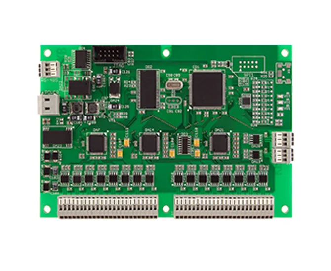
A PCB assembly process is the set of manufacturing operations used to install electronic components on a printed circuit board and create the electrical and mechanical connections required for the board to function. Depending on the design, this may involve automated component placement, solder paste printing, reflow soldering, lead insertion, wave or selective soldering, inspection, and electrical or functional testing.
PCB fabrication and PCB assembly are related but distinct activities. Fabrication produces the bare board, including its copper layers, traces, vias, solder mask, and surface finish. Assembly installs the components onto that board. A successful project needs both stages to work together: a well-fabricated PCB can still produce a poor finished assembly if the footprint design, soldering process, component quality, or inspection plan is inadequate.
When choosing the right PCB assembly process, treat manufacturability as an engineering decision rather than a purchasing detail. The process should fit the components, the product enclosure, the expected environment, and the required production rate.
The Main PCB Assembly Processes
1. Surface Mount Technology (SMT)
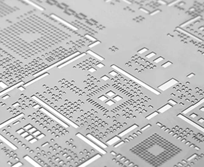
SMT places components directly onto pads on the PCB surface. In a typical process, solder paste is printed onto the pads, a placement machine positions components, and the board passes through a reflow oven to form solder joints. Additional inspection and testing follow as required.
SMT is generally the best starting point for compact electronic products, dense digital circuits, and designs containing large numbers of small passive components and integrated circuits. Automated placement supports repeatable production and high throughput when the board and component mix are suitable.
SMT is not automatically the best choice for every component. Large connectors, certain power components, or parts subject to significant mechanical loading may need a different mounting approach. Fine-pitch and bottom-terminated packages also demand appropriate footprint design and inspection capabilities.
2. Through-Hole Technology (THT)
Through-hole technology, also called through-hole assembly, inserts component leads through drilled PCB holes before soldering them to pads. Depending on the design and production setup, soldering may use wave soldering, selective soldering, or a controlled manual process.
THT is useful for selected connectors, terminal blocks, leaded power components, and products where lead-through-board mounting provides a practical mechanical advantage. It may also be appropriate for established designs that rely on specific leaded components.
The trade-off is that holes consume board area and can constrain routing. Component insertion and additional soldering operations may also increase manufacturing time. We recommend retaining through-hole parts where they serve a defined purpose, rather than using THT across a board by default.
3. Mixed-Technology Assembly
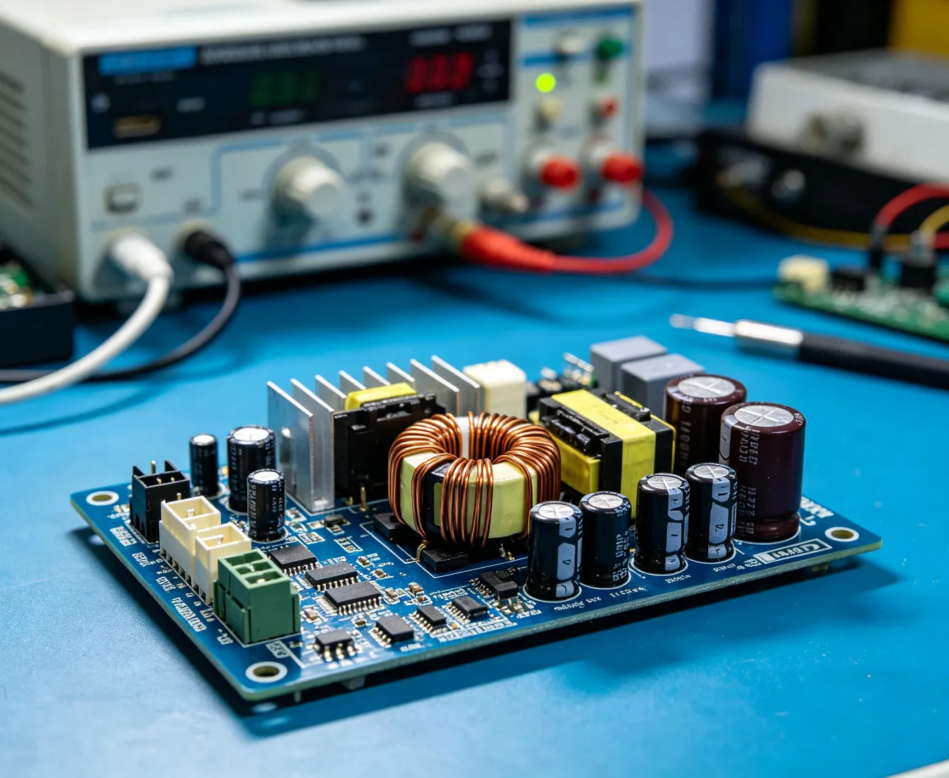
Mixed-technology assembly combines SMT and through-hole components on the same PCB. It is often the best practical solution when a board contains dense logic devices alongside connectors, terminal blocks, or components that benefit from through-hole mounting.
For example, an industrial controller may use SMT for processors, memory, resistors, and capacitors, while field-wiring terminals remain through-hole. This design can preserve board density without compromising the mechanical needs of the interfaces.
The challenge is process coordination. The manufacturer must select a suitable sequence for reflow, insertion, wave or selective soldering, inspection, and testing. Component temperature limits and the risk of disturbing previously soldered joints must be considered before production.
Quick Summary: Which PCB Assembly Process Fits Your Product?
Product or project requirement
Recommended starting point
Why it fits
What to verify
Compact consumer electronics
SMT
Supports dense layouts and automated placement.
Package size, fine-pitch capability, inspection access, and thermal design.
Industrial controller with field connectors
Mixed assembly
Combines compact SMT logic with suitable leaded interfaces.
Mechanical loading, soldering sequence, and connector accessibility.
Early-stage prototype
SMT, THT, or mixed, depending on the design
Allows process selection around component availability and engineering changes.
Prototype quantity, lead times, test coverage, and likely redesigns.
High-volume electronic product
Usually SMT-led or mixed
Automation can improve repeatability and throughput when the design is suitable.
Yield, line capacity, sourcing stability, tooling, and total unit cost.
Board with mechanically loaded components
THT or mixed, subject to engineering review
Through-hole mounting may provide useful lead anchoring.
Actual forces, vibration, mounting support, and solder-joint design.
Medical or other quality-sensitive product
Process selected from documented requirements
Process control and validation matter more than a generic technology preference.
Applicable standards, traceability, risk management, and test evidence.
Short delivery schedule
Whichever qualified process is available and appropriate
A ready production route and available components can reduce delays.
Material readiness, capacity, inspection, and realistic turnaround time.
This table is a starting point, not a substitute for a design review. The same product category can require different assembly routes depending on component packages, operating environment, and production requirements.
Seven Factors That Determine the Right PCB Assembly Process
1. Component types and package density
Start with the bill of materials (BOM). Count the SMT components, through-hole parts, fine-pitch devices, bottom-terminated packages, large connectors, and any components with unusual thermal or mechanical requirements. The component mix is often the clearest indicator of which assembly route is practical.
A board with hundreds of small resistors and integrated circuits is usually better suited to SMT than a manual through-hole process. A board containing SMT logic and large field-wiring terminals may benefit from mixed assembly. If a component is available in both SMT and through-hole versions, compare its electrical ratings, footprint, thermal performance, mechanical support, and availability before deciding.
2. Product function and operating environment
Consider the conditions the finished product will face. Temperature variation, vibration, shock, moisture, contamination, and repeated connector use can affect component and solder-joint reliability. The assembly process must support the intended environment, but it cannot compensate for inadequate mechanical design or unsuitable materials.
For heavy-duty applications, review the mounting system, enclosure, PCB supports, connector retention, and strain relief alongside the solder joints. A robust product is the result of a complete design and manufacturing system, not a single technology choice.
3. PCB size, layer count, and routing constraints
Through-hole components require drilled holes, which can reduce available routing space and influence the placement of copper features across multiple layers. SMT generally gives designers more flexibility for dense component placement because it avoids the same lead-hole requirements.
However, board size and layer count do not determine the assembly process by themselves. The design must also consider component spacing, thermal management, soldering access, and whether both sides of the board will carry components. If the layout is still being developed, a PCB design support service can help identify manufacturability issues before fabrication files are released.
4. Production volume and demand forecast
Prototype, pilot, and high-volume builds have different priorities. A prototype may prioritise fast engineering feedback and easy changes. A high-volume programme needs repeatable production, stable component supply, predictable cycle time, and a cost structure that remains competitive across the planned quantity.
Do not select a process based only on the first order. If the product is expected to scale, discuss the forecast with the manufacturer before approving the layout. A design that is convenient for a handful of engineering samples may not be efficient for tens of thousands of units.
5. Reliability, quality requirements, and testing
Define the required workmanship criteria and testing scope before requesting quotations. Some products may need visual inspection and basic electrical checks, while others require automated optical inspection (AOI), X-ray inspection, in-circuit testing, functional testing, or additional qualification activities.
The appropriate plan depends on component packages, failure consequences, customer requirements, and applicable regulations or standards. A fine-pitch or bottom-terminated component may require inspection methods beyond ordinary visual checks. A quality-sensitive application also needs traceability and documented change control where required.
6. Component availability and lifecycle risk
A technically suitable component is not necessarily a commercially safe choice if it has long lead times, uncertain lifecycle status, or limited approved alternatives. Component shortages can disrupt production regardless of the selected assembly process.
Before freezing the design, identify critical components and agree on an approved-substitution procedure. Alternate components must be reviewed for electrical characteristics, package dimensions, thermal behaviour, and footprint compatibility. A substitute should never be introduced into production solely because it is available without the required approval.
7. Delivery schedule and engineering flexibility
Fast turnaround depends on more than the assembly line. PCB fabrication, component procurement, stencil preparation, programming, tooling, inspection, and test development all affect the schedule. A supplier promising a short assembly time may still be waiting for critical components.
For early-stage projects, a quick-turn PCB service can help shorten development cycles when the required materials and manufacturing capacity are available. Confirm what the quoted lead time includes, when it begins, and whether testing and delivery are part of the commitment.
SMT vs. Through-Hole vs. Mixed Assembly: Comparison Table
Evaluation factor
SMT
Through-hole (THT)
Mixed assembly
Component density
Generally best for compact, dense layouts
Can be limited by drilled-hole and lead-spacing requirements
Balances dense SMT placement with selected leaded parts
Automation
Highly suitable for automated placement and reflow
Insertion and soldering automation varies by component and process
Requires coordinated process stages
Mechanical mounting
Depends on package, pads, reinforcement, and product design
Can provide useful mechanical anchoring for selected components
Allows mounting technology to vary by component
Thermal performance
Depends on package, copper design, and thermal path
Depends on component construction, lead design, copper, and cooling
Must be assessed component by component
Inspection
AOI is commonly useful; some packages may need X-ray
Visual inspection and process-specific checks are important
May need several inspection methods
Rework
Small or dense packages may require specialised equipment
Some parts are accessible, but desoldering can damage plated holes
Rework depends on package and process sequence
Production economics
Often advantageous for high-volume, dense designs
Can be costly if many parts require extra insertion and soldering
Often justified when each component benefits from a different method
Typical fit
Consumer electronics, computing, compact control boards
Selected connectors, leaded power parts, certain legacy designs
Industrial control, power electronics, and complex assemblies
In most professional situations, SMT is the starting point for compact modern electronics, but the final process should be determined by the component mix. Mixed assembly is not a compromise by default; it is often the most rational solution when the product has different electrical and mechanical needs.
Inspection, Testing, and Reliability: What Should Be Included?
A PCB assembly process should include a defined method for confirming that the board has been assembled correctly and meets its functional requirements. Inspection and testing are not interchangeable. Inspection looks for visible or otherwise detectable assembly defects; electrical and functional tests establish whether the board behaves as required under the selected test conditions.
Automated optical inspection (AOI)
AOI uses imaging and software to identify potential defects such as component misalignment, missing components, polarity errors, and some solder-joint issues. It is especially useful in SMT production, where small components and high placement density make consistent manual inspection difficult.
AOI has limits. It cannot reliably see every hidden solder joint or prove that a circuit performs its intended function. Learn more about PCB AOI inspection when deciding how visual inspection fits into the production plan.
X-ray inspection
X-ray inspection can help assess hidden solder joints, including connections beneath certain bottom-terminated packages and ball-grid-array devices. Whether X-ray is necessary depends on package type, risk, customer requirements, and the available inspection strategy. It should be selected to address a defined inspection need, not simply added to every order without considering value.
For boards containing components with hidden solder joints, discuss PCB X-ray inspection with the assembly provider before production. The inspection plan should identify which components need examination and what acceptance criteria apply.
Electrical and functional testing
Electrical testing may include continuity and isolation checks, while functional testing evaluates the board's behaviour under specified operating conditions. In-circuit testing may be appropriate where the design supports suitable test access and fixture development. The right test method depends on the product, the available test points, expected fault modes, and the consequences of failure.
China 365PCB offers a PCB electrical testing service for customers evaluating electrical verification requirements. Confirm exactly which tests are included, the test limits, the sample or production coverage, and the reporting provided.
Use standards as defined acceptance criteria
Industry standards such as IPC-A-610 and IPC J-STD-001 are commonly used to establish electronic assembly acceptability and soldering requirements. The correct standard, revision, class, and contractual acceptance criteria should be agreed upon by the customer and manufacturer. A product's required quality level should be established from its intended use and applicable obligations, not inferred from a generic statement that the assembly is high quality.
How Production Volume Changes the Decision
Prototype and engineering samples
For prototypes, speed of learning is often more valuable than the lowest theoretical unit cost. The process should allow the team to validate component selection, electrical behaviour, mechanical fit, and assembly feasibility. If the design is likely to change, avoid unnecessary tooling or process commitments before the key engineering questions have been resolved.
However, prototype builds should still use representative components and realistic manufacturing controls wherever possible. A prototype assembled with an improvised process may not reveal defects that appear in automated production. Ask the manufacturer which elements of the prototype process will carry over to the production build and which need to be revalidated.
Pilot production
Pilot builds bridge engineering and volume manufacturing. They should confirm that the BOM is stable, the process sequence is practical, inspection coverage is sufficient, and the production test method works as intended. This is the stage to resolve recurring assembly defects before they affect a larger order.
High-volume production
For larger quantities, process repeatability and supply-chain stability have a major effect on unit economics. SMT can offer strong throughput for suitable component mixes, but the production plan must also account for changeovers, feeders, stencils, programming, test time, scrap, and rework.
When demand is predictable and the design is mature, compare the quotation and manufacturing plan for high-volume PCB production. Confirm the planned capacity, material commitments, yield-monitoring approach, and change-control process before placing a long-term order.
PCB Assembly Cost-Benefit Analysis
The total cost of PCB assembly is made up of more than the price of soldering components onto a board. A realistic comparison should include PCB fabrication, component procurement, setup, stencils, programming, insertion, soldering, inspection, testing, rework, scrap, logistics, and the cost of delayed delivery.
When SMT can reduce cost
For a board containing many small components, automated SMT placement can reduce repetitive handling and improve throughput. The benefit becomes more significant when production volume is sufficient to spread setup costs across many units. However, fine-pitch packages, special materials, or complex inspection requirements can affect the overall cost.
When through-hole or mixed assembly can be worth the extra cost
Through-hole assembly may be justified when the component's mounting requirements make SMT unsuitable or when the design relies on a leaded package that meets the product's needs. Mixed assembly can avoid forcing all components into one technology, potentially preserving mechanical performance while retaining SMT efficiency for the rest of the board.
Compare equivalent quotations
When reviewing supplier offers, make sure the quotations cover the same PCB revision, BOM, quantity, approved components, inspection, testing, packaging, and delivery terms. A low quote that excludes X-ray, functional testing, component traceability, or required documentation may not represent the best value.
Practical recommendation: ask for a quotation that separates one-time setup costs from recurring unit costs. If the process is not yet fixed, request an engineering review of feasible alternatives and compare the cost of each complete manufacturing route. Do not compare SMT and through-hole unit prices without considering the components and operations included.
Choosing a PCB Assembly Process by Industry
Consumer electronics
Compact consumer products commonly benefit from SMT because size, component density, and automated production are important. The design may still include through-hole components for connectors or other interfaces where their package and mechanical properties are appropriate. See the considerations for consumer electronics PCB projects.
Automotive electronics
Automotive applications can involve temperature variation, vibration, demanding lifecycle expectations, and specific qualification requirements. The assembly process must follow the product's engineering requirements and applicable customer or industry standards. Technology selection alone does not establish automotive suitability. Review the requirements for the intended automotive PCB application early in development.
Medical electronics
Medical devices vary significantly in function and risk. The required process controls, traceability, validation, and testing depend on the device, its intended use, and applicable regulatory obligations. A manufacturer should understand the customer's quality requirements and document the agreed production and verification plan. For relevant projects, review medical PCB assembly requirements with the engineering and quality teams.
Industrial control systems
Industrial control boards often combine dense logic with terminal blocks, power interfaces, and connectors. Mixed assembly may be suitable because it supports SMT components while retaining through-hole mounting for selected field interfaces. The design should account for the operating environment, installation method, service access, and the loads applied to external connectors. See industrial control PCB solutions for this application category.
Telecommunications and LED lighting
Telecommunications hardware may prioritise high component density, signal integrity, thermal performance, and consistent manufacturing. LED lighting boards may place greater emphasis on thermal management, current handling, and long-term operating conditions. Both applications require technology selection to follow the electrical and mechanical design, rather than a one-size-fits-all assembly rule.
How to Choose a PCB Assembly Partner
The right PCB assembly partner should review the design, explain process trade-offs, and provide a production plan that matches the product's requirements. A supplier that simply accepts files and quotes a price may not identify problems until the board reaches assembly.
Questions worth asking before you place an order
Can the manufacturer support SMT, through-hole, and mixed-technology assembly for this component mix?
Which soldering methods are available, and how will the assembly sequence be determined?
Can the engineering team review the BOM, footprints, panelisation, and assembly drawings before production?
What inspection methods are available, and which components or joints require AOI or X-ray?
What electrical or functional tests are included in the quotation?
How are component substitutions approved and documented?
Which workmanship standards, acceptance criteria, and traceability requirements will apply?
What is included in the quoted lead time, and when does the schedule begin?
How will engineering changes, nonconforming parts, and production defects be handled?
Ask for a clear response rather than relying on broad claims about quality or speed. A good manufacturing partner should be able to explain what is included, what is excluded, and which assumptions could change the price or schedule.
Evaluate turnkey versus consigned assembly
In turnkey assembly, the supplier manages some or all of the component sourcing alongside fabrication and assembly, according to the agreed scope. In consigned assembly, the customer supplies the components. Neither model is universally better.
Turnkey sourcing can reduce the coordination burden for the customer, but it requires transparent component approval, traceability, and substitution control. Consigned assembly can provide more direct control over sourcing, but the customer must manage material availability, packaging, shortages, and delivery to the assembly facility. Compare the total responsibilities and risks, not just the headline service fee.
PCB Assembly Services from China 365PCB
China 365PCB provides printed circuit board assembly services for projects ranging from prototypes to full-scale production. Its stated capabilities include surface mount technology, through-hole technology, and mixed-technology assembly, with component placement, soldering, and testing arranged around project requirements.
For customers deciding how to choose the right PCB assembly process, the useful starting point is a complete technical review. Share the PCB files, BOM, expected quantity, assembly drawings, quality requirements, and target delivery schedule. These details help establish which manufacturing route is appropriate and identify any information needed before a firm quotation can be prepared.
For projects requiring a new or modified board, a custom PCB service may be relevant alongside assembly. The fabrication and assembly stages should be reviewed together so that footprints, board materials, hole dimensions, soldering access, and test requirements support the same production plan.
When evaluating a provider, confirm the specific capabilities and quality controls required for your product. Request clarification on inspection coverage, electrical testing, material sourcing, production lead time, and documentation before committing to an order. This is particularly important when the product has strict reliability or customer-approval requirements.
Common Mistakes When Choosing a PCB Assembly Process
Choosing by unit price alone
A low initial price can hide missing inspection, testing, setup, or material costs. Compare the complete manufacturing scope and the expected cost of rework or delayed delivery.
Waiting until after layout completion to involve the manufacturer
Late review can reveal inaccessible solder joints, unsuitable footprints, poor panelisation, or components that are difficult to source. Involve the assembly provider while design changes are still manageable.
Assuming SMT always means better quality
SMT is highly effective for many designs, but quality depends on process capability, component selection, layout, soldering, inspection, and testing. A well-controlled mixed assembly may be more appropriate than an all-SMT design that compromises component mounting.
Assuming through-hole is always more reliable
Through-hole leads can improve mechanical anchoring for selected parts, but they do not guarantee reliability. Verify the mechanical design and solder-joint requirements for the actual operating environment.
Leaving testing requirements vague
Terms such as “fully tested” are insufficient without a defined scope. Specify whether the order includes AOI, X-ray, electrical testing, functional testing, sampling, or production-wide checks, and identify the expected reports.
Ignoring the production ramp
A process that works for a small prototype may require different fixtures, programming, material planning, or inspection coverage at volume. Discuss forecast demand and the planned ramp before the design is released.
Expert Recommendation: Choose the Process That Fits the Whole Product
To choose the right PCB assembly process, begin with the component mix and product requirements, then validate the manufacturing route with the supplier. SMT is usually the strongest baseline for dense electronic designs. Through-hole remains appropriate where selected components benefit from lead-through-board mounting or where a proven legacy design should not be changed without a clear reason. Mixed assembly is often the best solution when both technologies serve different needs on the same board.
Use this practical decision sequence before approving the process:
Freeze the requirements, not the manufacturing method. Document electrical performance, mechanical loads, environment, size, lifecycle, and testing needs.
Review the BOM and footprints. Identify which components are available in suitable SMT and through-hole packages, and confirm critical dimensions.
Match the process to production volume. Account for prototypes, pilot builds, forecast demand, and future scaling.
Define inspection and testing. Specify the acceptance criteria and test coverage needed to verify the assembled board.
Compare complete quotations. Include fabrication, materials, setup, assembly, inspection, testing, logistics, and documentation.
Run a representative build. Use prototype or pilot production to identify process issues before committing to large quantities.
For beginners, the main lesson is that no single assembly technology is best for every board. For commercial users, the decision should reflect total cost, supply risk, quality expectations, and product lifecycle. For high-reliability applications, process selection must be supported by documented requirements, appropriate inspection, and validation.
China 365PCB can be considered as a manufacturing partner when evaluating PCB assembly options from prototype through production. The strongest starting point is a technical discussion based on the actual design data, rather than a generic request for the cheapest assembly process.
Frequently Asked Questions About PCB Assembly Processes
What is the best PCB assembly process for most products?
SMT is usually the starting point for compact, component-dense electronic products because it supports automated placement and efficient use of board area. Through-hole or mixed assembly may be more appropriate for selected connectors, power components, and mechanically demanding parts. The final choice depends on the design and production requirements.
What is the difference between SMT and through-hole assembly?
SMT components are mounted on surface pads, while through-hole components have leads inserted through drilled holes and soldered to the PCB. SMT generally supports higher component density and automated placement. Through-hole can be useful when a leaded component or mounting arrangement better meets mechanical requirements.
Is mixed-technology PCB assembly worth the extra complexity?
It is often worth considering when a board needs dense SMT logic and selected through-hole components. Mixed assembly allows each component to use a suitable mounting technology, but the process sequence, soldering method, inspection, and rework requirements must be planned carefully.
How does production volume affect the PCB assembly process?
Prototype production prioritises engineering feedback, flexibility, and component availability. High-volume production places greater emphasis on automation, repeatability, yield, sourcing stability, and unit economics. A design intended to scale should be reviewed with the future production volume in mind.
What inspection methods should a PCB assembly manufacturer offer?
Depending on the design, relevant methods may include visual inspection, automated optical inspection, X-ray inspection for certain hidden joints, electrical testing, and functional testing. The required combination depends on package types, risk, customer requirements, and applicable standards.
How can I reduce PCB assembly costs without lowering quality?
Improve manufacturability early, select readily available components where suitable, avoid unnecessary process complexity, and define the required inspection and testing scope clearly. Compare complete quotations and evaluate yield and rework risks rather than selecting a supplier on the lowest initial unit price.
What files are needed for a PCB assembly quotation?
Most quotations require PCB fabrication files, a BOM with manufacturer part numbers, assembly drawings, quantities, required lead time, and quality or testing requirements. Include approved alternatives, special handling instructions, and any applicable standards or customer specifications.
Should I use turnkey or consigned PCB assembly?
Turnkey assembly can reduce sourcing and coordination work when the supplier manages component procurement. Consigned assembly can offer greater direct sourcing control but requires the customer to manage material availability and delivery. Choose based on sourcing capability, traceability, workload, and total cost.
When should I use quick-turn PCB assembly?
Quick-turn services are useful when prototypes or urgent builds are needed and the required materials and production capacity are available. Confirm what the turnaround time covers, whether testing is included, and whether the accelerated schedule leaves enough time for engineering review.
How do I know whether my PCB needs X-ray inspection?
X-ray may be useful for inspecting hidden solder joints under certain packages, such as BGAs and some bottom-terminated components. The need depends on package design, process risk, customer requirements, and the inspection strategy. Agree on the scope and acceptance criteria with the manufacturer before production.
Final takeaway: The right PCB assembly process is the one that meets your product's electrical, mechanical, quality, schedule, and cost requirements without adding unnecessary complexity. Use SMT for dense designs, through-hole where it provides a clear component-level benefit, and mixed assembly when both are needed. Bring the manufacturer into the decision early, define inspection and testing requirements, and validate the process before scaling production.
David Li
David Li is the Technical Communications Director at China 365PCB, with over 15 years of hands-on experience in the PCB and electronics manufacturing industry. Holding a Master’s degree in Electrical Engineering, he has worked extensively in both R&D and manufacturing roles at leading multinational electronics firms in Shenzhen before joining our team.
His expertise spans high-speed digital design, advanced packaging (HDI, Flex), and automotive-grade reliability standards. David is passionate about bridging the gap between design intent and production reality—a philosophy that aligns perfectly with 365PCB’s mission to deliver seamless, rapid, and fully-integrated manufacturing solutions.
Follow David’s insights on PCB technology trends and best practices here on the 365PCB Knowledge Hub.
We use cookies to offer you a better browsing experience, analyze site traffic and personalize content. Part of the tracking is necessary to ensure SEO effectiveness, By using this site, you agree to our use of cookies.
Visit our cookie policy to learn more.
 English