English
The four core assembly technologies for PCB are Surface Mount Technology (SMT), Through-Hole Technology (THT), mixed-technology assembly and advanced package assembly methods such as Ball Grid Array (BGA) and other fine-pitch interconnections. They are not interchangeable. Each solves a different manufacturing problem, and choosing the wrong process can increase assembly cost, complicate inspection and reduce product reliability.
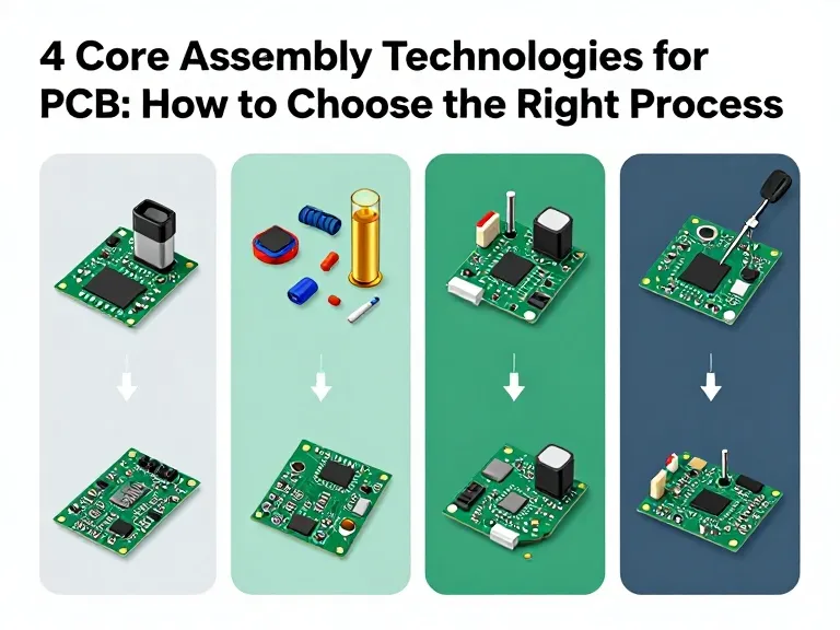
The four important PCB assembly approaches are SMT, THT, mixed SMT and THT assembly, and advanced package assembly for components such as BGA, QFN and fine-pitch ICs. SMT is the preferred option for most modern, compact electronic products because it supports high-speed automated placement and dense layouts. THT remains valuable for connectors, large components and applications requiring strong mechanical anchoring. Mixed assembly is common in practical electronic products that combine both component types. Advanced package assembly requires tighter process control, specialized inspection and experienced manufacturing support.
From our experience, the best PCB assembly process is determined by the component package, electrical design, mechanical requirements, production volume and quality target—not by which technology sounds more advanced. A board built entirely with SMT may be ideal for a compact consumer device, while an industrial controller with large connectors and power components may need both SMT and through-hole soldering.
Which PCB Assembly Technology Should You Choose?
For most new electronic products, we recommend SMT as the primary assembly technology. It offers efficient automated placement, supports small components and enables high component density. However, SMT should not be forced onto every component. Through-hole assembly remains the better choice when a component requires mechanical retention, has a suitable through-hole termination or must withstand significant insertion or operating forces.
In most professional situations, the practical solution is a process selected component by component. A mixed-technology board can use SMT for resistors, capacitors and ICs while reserving through-hole assembly for connectors, switches, transformers or selected power components. Advanced packages such as BGA then require their own process controls and inspection strategy.
The following guide explains how each technology works, where it performs best, what it costs and how to evaluate a PCB assembly manufacturer before production.
What Are PCB Assembly Technologies?
PCB assembly technology refers to the manufacturing methods used to attach electronic components to a printed circuit board and create a functioning electronic assembly. The process includes component placement, soldering, inspection and, where required, electrical or functional testing.
The assembly technology affects more than how components are attached. It influences PCB layout, component selection, stencil design, production equipment, inspection requirements, repairability and final manufacturing cost.
How PCB assembly technologies work
In SMT, components are placed directly onto conductive pads on the PCB surface and soldered, typically through a reflow process. In THT, component leads pass through drilled holes and are soldered to pads, commonly using wave soldering or selective soldering in production. Mixed-technology assembly combines these methods on one board. Advanced package assembly focuses on demanding component structures such as BGA, QFN and fine-pitch devices, which require careful placement, soldering and inspection.
It is important to understand that BGA is not a completely separate alternative to SMT. BGA is a component packaging and interconnection technology that is assembled using a specialized SMT process. It is treated separately here because its manufacturing and inspection requirements are more demanding than those of ordinary chip components.
1. Surface Mount Technology (SMT)
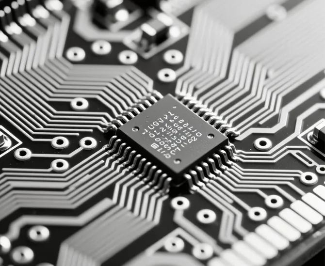
Surface Mount Technology is the dominant assembly method for most modern electronic products. Instead of inserting component leads through drilled holes, SMT places components directly onto pads on the PCB surface. Solder paste is printed onto the pads, components are positioned by automated pick-and-place machines, and the board passes through a reflow oven to form solder joints.
SMT is popular because it supports high component density, automated production and compact product designs. It is particularly effective for boards containing large numbers of resistors, capacitors, diodes, transistors and integrated circuits.
How the SMT assembly process works
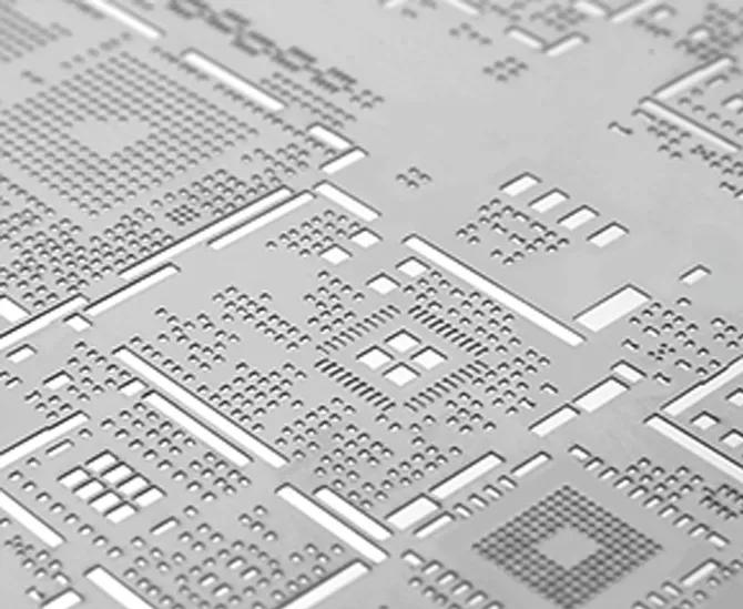
Solder paste printing: A stencil transfers solder paste onto the PCB pads.
Solder Paste Inspection: SPI equipment checks paste deposits for issues such as volume, height and alignment.
Component placement: Automated pick-and-place machines position components onto the solder paste.
Reflow soldering: The PCB passes through a controlled thermal profile to melt the solder and form electrical and mechanical connections.
Post-reflow inspection: AOI and other suitable methods identify visible or hidden assembly defects.
Electrical or functional testing: The assembled board is tested according to product requirements.
Benefits of SMT
High production efficiency: Automated placement supports repeatable assembly at commercial volumes.
Compact design: Smaller component packages and surface-mounted connections support dense PCB layouts.
Both-side assembly: Components can be mounted on both PCB surfaces when the design and process allow it.
Broad component availability: Many modern electronic components are supplied in SMT packages.
Good scalability: SMT is suitable for prototypes, small batches and mass production when the process is properly configured.
Limitations of SMT
SMT is not automatically the best solution for every component. Some large or mechanically stressed components may need stronger anchoring than a surface-mounted joint provides. Fine-pitch devices also demand accurate stencil printing, placement and reflow control. A poorly designed SMT board can create bridging, tombstoning, insufficient solder or component alignment problems.
For heavy-duty applications, consider whether connectors, large capacitors, transformers and other mechanically loaded parts should use through-hole connections or additional mechanical support.
When should you choose SMT?
We recommend SMT for consumer electronics, compact control boards, telecommunications equipment, computing products, LED drivers and most electronic designs using modern surface-mount components.
For example, a compact wireless controller with hundreds of small passive components and several ICs is a natural SMT application. Automated placement is more practical than manually inserting and soldering that component mix.
Explore 365PCB's SMT PCB assembly services for automated surface mount assembly covering prototypes and volume production.
2. Through-Hole Technology (THT)
Through-Hole Technology is a traditional PCB assembly method in which component leads are inserted through drilled holes in the board and soldered to pads on the opposite side. Although SMT has replaced THT for many component types, through-hole assembly remains important in products where mechanical strength, component size or connection design makes it a better option.
How through-hole assembly works
Components are inserted into designated PCB holes according to the assembly drawing. The leads are then soldered to the corresponding pads. Depending on the board design and production volume, soldering may use manual soldering, wave soldering or selective soldering.
Benefits of THT
Mechanical retention: Leads passing through the PCB can provide strong mechanical anchoring.
Suitable for larger components: Some connectors, transformers, switches and power components are designed for through-hole mounting.
Accessible repair: Many through-hole joints are relatively straightforward to inspect and rework.
Useful for high insertion forces: Components subject to repeated plugging, unplugging or mechanical stress may benefit from through-hole construction.
Practical for selected prototypes: Low-volume engineering builds may use hand insertion and soldering when automation is not justified.
Limitations of THT
THT requires drilled holes and consumes PCB routing space. It generally supports lower component density than SMT and can add assembly time when many components require manual insertion. Drilling and wave soldering also introduce process considerations that do not apply in the same way to standard SMT assembly.
For high-volume products, using THT for every component can increase board size and manufacturing cost unnecessarily. We recommend reserving it for components whose mechanical or electrical requirements justify the process.
When should you choose THT?
THT is a sensible choice for large connectors, power terminals, transformers, relays, switches and components that experience significant mechanical loading. It is also useful when a component is only available in a through-hole package or when the design requires a particular leaded connection.
For industrial control equipment, a board may use SMT for logic and signal processing while retaining through-hole terminals for field wiring. This arrangement provides compact electronics without compromising the mechanical requirements of external connections.
For projects involving demanding operating environments, review the relevant industrial control PCB applications and determine which components need stronger mechanical attachment.
3. Mixed SMT and THT Assembly
Mixed-technology assembly combines surface-mounted and through-hole components on the same PCB. It is common in real-world electronics because many products contain a combination of compact ICs, passive components, connectors and mechanically demanding parts.
Rather than forcing the entire design into one assembly method, mixed assembly allows the engineer to choose the most suitable technology for each component.
How mixed PCB assembly works
The exact process depends on the board layout and component sequence. A common arrangement is to assemble SMT components first using solder paste printing, automated placement and reflow soldering. Through-hole components are then inserted and soldered using selective soldering, wave soldering or manual processes where appropriate.
Some designs require through-hole components to be installed before or between SMT operations. In those cases, the manufacturer must plan the sequence carefully to avoid thermal damage, mechanical interference or contamination of previously assembled components.
Benefits of mixed assembly
Design flexibility: Engineers can choose component packages based on function and mechanical requirements.
Balanced performance: SMT supports compact logic circuits while THT supports selected connectors and mechanically stressed parts.
Practical component sourcing: The design can accommodate components available in different package formats.
Suitable for complex products: Many industrial, automotive and power electronics assemblies need both technologies.
Limitations of mixed assembly
Mixed assembly involves more process planning than a board using only one assembly method. The manufacturer must coordinate component insertion, soldering sequence, thermal exposure, fixture design and inspection. If the design is not planned for the production process, the additional operations can increase cost and create avoidable defects.
When is mixed assembly worth using?
Choose mixed assembly when your product has a genuine need for both component types. Industrial controllers, power management boards, communication equipment and certain automotive electronic modules are common examples.
For commercial users, the decision should be based on total product cost and reliability. A mixed board may cost more to assemble than a pure SMT board, but that additional cost can be justified if it provides the required mechanical strength or allows the use of components that are not practical in surface-mount form.
4. Advanced Package Assembly: BGA and Fine-Pitch Technology
Advanced package assembly covers components whose connection structures require more precise manufacturing and inspection than ordinary SMT parts. Examples include Ball Grid Array (BGA), fine-pitch QFP, Quad Flat No-lead (QFN) and other bottom-terminated packages.
These components are still generally assembled using SMT principles, but their small connection geometry and limited visual access make process control more demanding.
BGA assembly
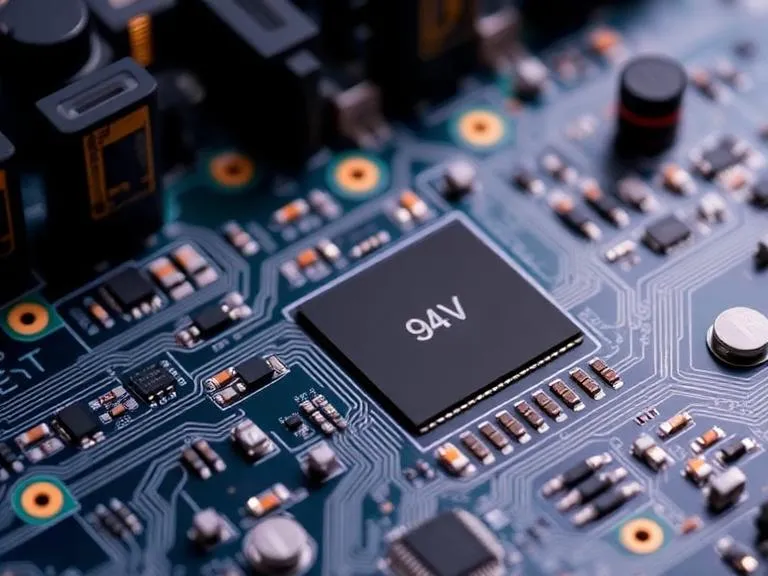
A BGA component uses an array of solder balls underneath the package rather than exposed leads around its edges. The solder balls connect the component to corresponding PCB pads during reflow. BGA packages can support high pin counts and compact layouts, making them useful in processors, memory devices, networking equipment and other advanced electronics.
The main challenge is that the solder joints are hidden beneath the package after assembly. Standard visual inspection cannot directly verify each joint. X-ray inspection is therefore commonly used to assess hidden connections, although X-ray results must be interpreted against suitable acceptance criteria.
Fine-pitch and QFN assembly
Fine-pitch components have closely spaced terminals, which increases sensitivity to solder paste volume, stencil alignment and placement accuracy. QFN packages use terminals around the underside perimeter and may include a central thermal pad. Their assembly requires suitable pad and stencil design, controlled paste deposition and an appropriate reflow profile.
Benefits of advanced package assembly
Supports high-density and high-performance electronic designs.
Enables compact packages with many electrical connections.
Supports processors, memory, RF and advanced communication components.
Can reduce board space compared with some larger leaded packages.
Limitations and manufacturing risks
Advanced packages require appropriate equipment, process knowledge and inspection capability. Common risks include insufficient solder, bridging, voiding, package warpage, placement errors and hidden joint defects. Rework can also be more difficult and may require specialized equipment and trained operators.
We recommend confirming BGA and fine-pitch capabilities before choosing a manufacturer. Ask for details about stencil design, placement accuracy, reflow profiling, X-ray inspection and rework procedures. A supplier's general claim that it supports SMT does not automatically prove that it can reliably assemble every advanced package.
Comparison of the 4 Core Assembly Technologies for PCB
The following table summarizes where each assembly technology offers the strongest practical value.
| Technology | How components connect | Main advantages | Main limitations | Best applications |
|---|---|---|---|---|
| SMT | Components solder directly onto PCB surface pads. | High automation, compact layouts, high placement density and scalable production. | Requires accurate printing and placement; some parts need additional mechanical support. | Consumer electronics, computing, telecom, LED and compact control boards. |
| THT | Component leads pass through drilled holes and are soldered. | Strong mechanical anchoring and accessible connections for many components. | Lower component density and additional drilling and insertion operations. | Connectors, terminals, transformers, relays and mechanically stressed components. |
| Mixed SMT and THT | Combines surface-mount and through-hole connections on one board. | Allows component-by-component process selection and broad design flexibility. | More complex assembly sequencing and process coordination. | Industrial controls, power electronics and complex commercial products. |
| Advanced package assembly | Specialized SMT connections such as BGA solder ball arrays and fine-pitch terminals. | High-density interconnection and support for advanced IC packages. | Demands tighter process control and specialized inspection or rework. | Processors, memory, networking, RF and high-performance electronics. |
Pros and Cons of the Four PCB Assembly Technologies
| Technology | Pros | Cons |
|---|---|---|
| SMT | Fast automated assembly; compact design; high component density; suitable for many production volumes. | Requires precise printing and placement; sensitive to process variation; some components need mechanical reinforcement. |
| THT | Strong mechanical attachment; practical for large components and connectors; often easier to rework. | Uses drilled holes; limits routing and component density; can increase assembly time. |
| Mixed assembly | Flexible component selection; balances compact electronics and mechanical strength. | More complex process planning; may require multiple soldering operations and additional inspection. |
| Advanced packages | Supports high pin counts and compact, high-performance designs. | Higher process sensitivity; hidden joints complicate inspection; specialized rework may be required. |
How the PCB Assembly Process Works
Although assembly sequences vary by design, most production workflows follow a controlled sequence from material preparation to final testing. Understanding the steps helps buyers assess whether a manufacturer has the right process capability for their product.
1. Engineering review and manufacturing preparation
The manufacturer reviews the PCB files, BOM, assembly drawings, component packages and production requirements. DFM and Design for Assembly (DFA) checks identify potential issues before materials enter production.
2. PCB fabrication and incoming inspection
The bare PCB is manufactured according to the approved stack-up, dimensions, copper features and surface finish. Incoming inspection checks that the boards meet the agreed specifications before assembly begins.
3. Solder paste printing and SMT placement
For SMT boards, solder paste is deposited through a stencil and components are placed using automated equipment. The placement program must match the approved component data and PCB revision.
4. Reflow or other soldering operations
SMT components are typically soldered through a controlled reflow process. Through-hole components may be soldered using wave soldering, selective soldering or manual methods depending on the design and production requirements.
5. Inspection and rework
AOI, X-ray, visual inspection and other methods are used according to the component types and product requirements. Defects are classified and reviewed before any rework is performed.
6. Electrical and functional testing
Testing verifies the board against defined electrical or functional requirements. Depending on the product, this may include continuity checks, short-circuit testing, in-circuit testing, programming and functional verification.
7. Final quality review and shipment
Completed assemblies are reviewed against the agreed acceptance criteria. Traceability records, inspection results and packaging requirements should be controlled before shipment.
How to Choose the Right PCB Assembly Technology
The right assembly method starts with the product requirements. We recommend evaluating the following factors before finalizing the PCB layout or requesting a manufacturing quotation.
1. Component package and availability
Review whether the selected components are SMT, through-hole or advanced packages. Check manufacturer datasheets, package dimensions, lead configuration and lifecycle status. If a critical component is only available in a particular package, the PCB design must accommodate it.
2. Electrical and thermal requirements
Power dissipation, current capacity, signal integrity and thermal management can influence component selection and assembly design. High-current connections and large power components may require special pad designs, heavier copper or mechanical support.
3. Mechanical stress and operating environment
Consider vibration, shock, connector insertion forces, temperature cycling and enclosure constraints. A compact SMT solution may be appropriate for a handheld device, while an industrial board with field wiring may need through-hole terminals or mechanical reinforcement.
4. Production volume
For prototypes and small batches, the most economical process may differ from the one used in mass production. SMT is highly suitable for automated production, while selected through-hole components may require manual or selective soldering. Ask the manufacturer to explain setup charges, programming costs, stencil costs and volume pricing.
5. Inspection and test requirements
Advanced packages may require X-ray inspection, while complex boards may need ICT or functional test fixtures. Include these requirements in the project plan before production rather than treating testing as an optional final step.
6. Total manufacturing cost
Compare the complete cost of the assembly process, not just the quoted price per board. Include PCB fabrication, components, stencil, setup, assembly, inspection, testing, rework risk, packaging and logistics. A slightly more expensive process may deliver better value if it reduces defects or supports a more reliable product.
For most new designs, start with SMT as the default and introduce THT only where component function or mechanical requirements justify it. If the board uses BGA, QFN or fine-pitch packages, qualify the supplier's process and inspection capability before committing to production.
Common Mistakes When Selecting PCB Assembly Technologies
Choosing SMT only to reduce cost
SMT is efficient, but it is not automatically the lowest-cost option for every component. If a connector experiences repeated mechanical loading, using a suitable through-hole package may reduce failure risk and long-term service costs.
Using through-hole components without considering board density
Through-hole components consume routing space and require drilled holes. Using them unnecessarily can increase PCB size and restrict layout options. Select THT based on a real mechanical or component requirement.
Ignoring BGA inspection requirements
BGA solder joints are hidden beneath the package. A visual inspection strategy alone is insufficient for assessing those connections. Confirm whether X-ray inspection and appropriate acceptance criteria are included in the manufacturing plan.
Finalizing the design before consulting the manufacturer
A layout that works electrically may still be difficult to manufacture. Ask the PCB assembly supplier to review the design before final release, especially when the board includes fine-pitch parts, dense routing, mixed assembly or unusual thermal requirements.
Comparing suppliers only by unit price
A low quotation does not prove that a supplier has the right equipment, engineering support or quality controls. Compare process capability, inspection resources, traceability, communication and total project cost.
Inspection, Testing and Quality Standards for PCB Assembly
Assembly technology alone does not determine product quality. The inspection and testing strategy must match the package types, product function and customer requirements.
Automated Optical Inspection (AOI)
AOI uses cameras and image-processing systems to identify visible defects such as missing components, polarity errors, alignment problems and certain soldering issues. It is useful for both SMT and mixed-technology boards, but it cannot reliably inspect every hidden connection.
See 365PCB's PCB AOI inspection service for information about optical inspection.
X-ray inspection
X-ray inspection helps evaluate hidden solder joints beneath packages such as BGA and certain bottom-terminated components. It can reveal issues that are not visible from the board surface. The results should be assessed using appropriate inspection criteria rather than relying on an image alone.
For advanced packages, consider a dedicated PCB X-ray inspection service.
Electrical testing
Electrical testing checks whether the assembled board meets defined electrical requirements. Depending on the design, this can include continuity, isolation, short-circuit detection and other test procedures. Functional testing may then verify that the board performs its intended operation under specified conditions.
For projects requiring additional verification, review 365PCB's PCB electrical testing service.
Follow relevant IPC requirements
IPC standards are widely used in electronics manufacturing to define requirements for soldered assemblies, workmanship and inspection. IPC-A-610 addresses acceptability of electronic assemblies, while J-STD-001 covers requirements for soldered electrical and electronic assemblies. The applicable revision, product class and customer-specific requirements should be agreed before production.
For automotive, medical and other regulated or high-reliability applications, additional sector-specific quality and regulatory requirements may apply. A generic statement that a board is manufactured to IPC standards does not replace a project-specific quality plan.
Which PCB Assembly Technology Fits Different Industries?
Different industries have different design priorities. The same assembly process may be suitable for one product but inappropriate for another because of operating temperature, vibration, electrical performance or product size.
| Industry | Common assembly considerations | Practical direction |
|---|---|---|
| Consumer electronics | Compact size, high component density and production efficiency. | SMT is usually the primary method. |
| Automotive electronics | Thermal cycling, vibration, reliability and traceability. | Use SMT or mixed assembly based on component and mechanical requirements; validate against applicable automotive requirements. |
| Medical electronics | Product risk, traceability, process validation and applicable regulatory controls. | Select assembly and testing methods according to the device's risk and quality requirements. |
| Industrial control | Field wiring, connectors, vibration and long operating life. | Mixed SMT and THT assembly is often practical. |
| Telecommunications | High-density circuits, signal performance and advanced IC packages. | SMT with qualified fine-pitch or BGA assembly capability. |
| LED lighting | Thermal management, current handling and reliable solder joints. | SMT is common; thermal design and component mounting need careful validation. |
| Solar and EV systems | Power handling, thermal stress and demanding operating environments. | Choose SMT, THT or mixed assembly based on electrical and mechanical loading. |
For application-specific requirements, explore 365PCB's pages for consumer electronics PCB, automotive PCB, medical PCB and telecommunication PCB solutions.
How to Choose a PCB Assembly Manufacturer
The supplier you select affects process stability, delivery performance and the amount of engineering support available during production. We recommend evaluating manufacturers on their actual capabilities rather than relying on general claims about advanced equipment.
Check SMT line capability
Ask about placement equipment, supported component sizes, fine-pitch capability, BGA experience, stencil printing, reflow profiling and inspection systems. If your board includes small packages or advanced ICs, request examples of relevant production experience.
Confirm THT and mixed-assembly capability
If the design includes through-hole components, ask whether the supplier supports manual insertion, wave soldering or selective soldering. Confirm how the assembly sequence is planned and how thermal exposure is controlled when both technologies are used.
Review engineering support
A good manufacturing partner should be able to review Gerber files, BOM data, component footprints and assembly drawings. It should identify manufacturability concerns before production and explain the practical implications of proposed changes.
365PCB's PCB design support services are relevant when a project needs engineering review before fabrication or assembly.
Check fabrication and assembly coordination
When the same supplier can coordinate PCB fabrication and assembly, it may be easier to resolve issues involving pad geometry, board thickness, surface finish, stack-up or assembly tolerances. This is particularly valuable for custom boards, advanced packages and quick-turn prototypes.
Explore custom PCB manufacturing when your project requires a board designed around specific electrical, mechanical or production requirements.
Ask about quality documentation and traceability
Confirm how the manufacturer records material batches, PCB revisions, inspection outcomes, rework and test results. For regulated or high-reliability applications, define the required documentation and traceability level before production begins.
Compare total cost and delivery capability
Ask for a quotation that clearly identifies tooling, stencil, setup, assembly, inspection, testing and logistics costs. Also confirm the lead time for materials, PCB fabrication, assembly and final testing. The lowest quoted unit price is not necessarily the lowest-cost project if it creates rework, delays or quality problems.
SMT PCB Assembly Services from 365PCB
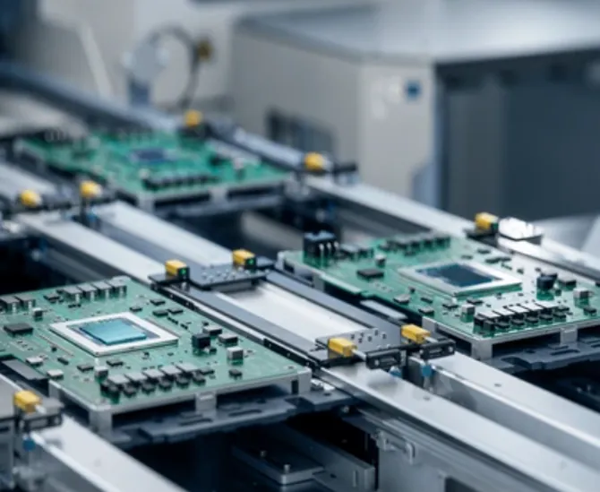
365PCB provides SMT PCB assembly services using automated SMT production lines for projects ranging from prototypes to volume production. Its stated capabilities include assembly of 0402 chip components, fine-pitch ICs and complex BGA packages, with support for lead-free RoHS and leaded soldering according to project requirements.
SMT PCB Assembly Services
365PCB offers high-speed surface mount technology assembly for electronic products requiring automated component placement, soldering and quality inspection. The service supports prototype and production requirements, with no minimum order quantity stated for its SMT assembly offering.
For buyers, the important point is to match the manufacturer's capability to the actual board. If your design uses 0402 components, fine-pitch ICs or BGA packages, provide the full technical data and ask the supplier to confirm the relevant process and inspection plan before ordering.
When requesting a quotation from 365PCB, prepare the latest Gerber files, BOM, pick-and-place data, assembly drawings, target quantity, required soldering process and inspection or test requirements. If the project involves mixed SMT and THT assembly, identify the through-hole components and any mechanical or thermal constraints clearly.
Expert Recommendation: Which Assembly Technology Is Best?
For most modern electronic products, SMT should be the starting point because it supports compact designs and efficient automated assembly. However, the strongest manufacturing solution is rarely a blanket commitment to one technology.
Choose SMT when the product needs compact dimensions, automated placement and high component density.
Choose THT when components need strong mechanical anchoring, larger leads or a through-hole package.
Choose mixed assembly when the design combines compact surface-mounted electronics with connectors or components that benefit from through-hole mounting.
Choose advanced package assembly when the design requires BGA, QFN or fine-pitch components and the manufacturer can demonstrate suitable process and inspection capability.
For beginners, the priority should be a manufacturable PCB layout and a clear assembly drawing. For commercial users, focus on repeatability, production cost, traceability and test coverage. For heavy-duty applications, give mechanical retention, thermal performance and environmental validation the same attention as component placement density.
Our final recommendation is to involve the PCB assembly manufacturer before the design is frozen. A short engineering review can identify package, layout and process risks that are expensive to correct after fabrication. Choose the assembly technology that meets the product's real requirements, then qualify the supplier's ability to manufacture it consistently.
Frequently Asked Questions About PCB Assembly Technologies
1. What are the four main assembly technologies for PCB?
The four assembly approaches discussed here are Surface Mount Technology (SMT), Through-Hole Technology (THT), mixed SMT and THT assembly, and advanced package assembly for devices such as BGA, QFN and fine-pitch ICs. Advanced packages are generally assembled using specialized SMT processes but require additional process and inspection controls.
2. Which PCB assembly technology is most commonly used?
SMT is the most widely used approach for many modern electronic products because it supports compact component packages, automated placement and high production efficiency. However, THT and mixed assembly remain important for connectors, power components and parts exposed to mechanical stress.
3. What is the difference between SMT and THT?
SMT places components directly onto pads on the PCB surface and solders them, usually through reflow. THT inserts component leads through drilled holes and solders them to pads. SMT generally supports higher component density and automation, while THT can provide stronger mechanical anchoring for selected components.
4. Is SMT better than through-hole assembly?
SMT is generally better for compact, high-density electronic designs and automated production. Through-hole assembly is better for some large components, connectors and applications that need mechanical retention. The correct choice depends on component design, operating conditions and product requirements.
5. What is mixed-technology PCB assembly?
Mixed-technology assembly combines SMT and THT components on the same PCB. It allows designers to use surface-mounted components for compact circuits and through-hole components where mechanical strength or package availability makes them more suitable.
6. What is BGA assembly?
BGA assembly is the process of mounting a Ball Grid Array component onto a PCB using solder balls arranged beneath the package. It is a specialized SMT application that supports high-density connections. Because the solder joints are hidden, X-ray inspection is commonly used to assess them.
7. Does every PCB assembly project need AOI and X-ray inspection?
Not every board requires both methods. AOI is useful for visible component and solder defects, while X-ray is valuable for hidden joints such as those under BGA packages. Select inspection methods according to the component technology, product risk and customer acceptance requirements.
8. What files are needed for a PCB assembly quotation?
Most manufacturers will request Gerber or other fabrication data, a BOM, pick-and-place files, assembly drawings, board quantity and project specifications. Include component datasheets, approved alternates, inspection requirements and functional test information when relevant.
9. Can 365PCB assemble prototypes and mass-production PCBs?
365PCB states that its SMT PCB assembly services support projects from prototype to volume production. Buyers should provide their board files, BOM, component package details and quantity so the manufacturing team can confirm process suitability, lead time and quotation requirements.
References
IPC-A-610: Acceptability of Electronic Assemblies — Industry workmanship criteria for evaluating electronic assemblies. Confirm the applicable revision and acceptance class for the project.
IPC J-STD-001: Requirements for Soldered Electrical and Electronic Assemblies — Requirements for soldered electronic assemblies, including materials and process considerations.
IPC — Association Connecting Electronics Industries — Industry standards, training and technical resources for PCB design, fabrication and assembly.
Final takeaway: The four core assembly technologies for PCB serve different manufacturing needs. SMT is the best starting point for most modern compact electronics, THT remains essential for selected mechanically demanding components, mixed assembly provides practical flexibility, and advanced package assembly supports dense and high-performance designs. The right decision comes from matching the technology to the product and selecting a manufacturer with proven process and inspection capability.