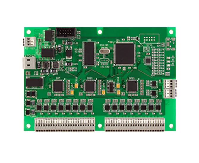
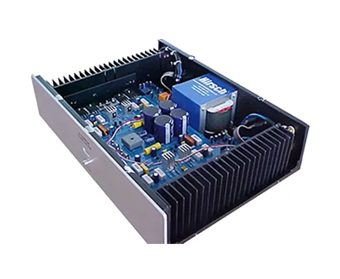
A finished electronic product can use a well-designed circuit, carefully selected components, and a professionally fabricated PCB yet still perform poorly if the assembly process is inconsistent. PCB assembly quality affects electrical stability, signal integrity, thermal behavior, mechanical durability, production yield, and the likelihood of field failures. A board that passes a basic power-on test is not necessarily a board that will perform reliably over months or years of operation.
For OEMs, product developers, and procurement teams, the practical priority is to evaluate PCB assembly quality as part of the complete product design. Component placement, solder-joint integrity, process control, inspection coverage, and functional testing all influence the result. Choosing a supplier on price or delivery speed alone can be a costly mistake if the production process cannot consistently meet the product's requirements.
Quick Answer: How Does PCB Assembly Quality Affect Product Performance?
PCB assembly quality affects whether components connect correctly, signals behave as intended, heat is managed properly, and the product withstands its operating environment. Poor assembly can cause intermittent faults, unstable power, communication errors, premature component failure, and expensive returns. We recommend choosing a PCBA supplier with documented process controls, suitable inspection methods, risk-based testing, component traceability, and a clear corrective-action process. The right quality plan should match the product's complexity and consequences of failure—not simply maximize the number of inspections.
Quick Summary Table: PCB Assembly Quality and Product Performance
Assembly quality factor
Possible effect on the final product
Recommended control
Component placement
Open connections, shorts, polarity errors, intermittent operation
Validated placement programs and appropriate optical inspection
Controlled soldering processes and risk-based joint inspection
Component authenticity
Unexpected electrical behavior, inconsistent quality, early failure
Qualified sourcing and suitable traceability
Thermal management
Overheating, performance drift, accelerated aging
Thermal design review and testing under representative loads
Signal and power integrity
Noise, communication errors, resets, unstable outputs
Layout review, correct assembly, and electrical validation
Inspection and testing
Defects escaping into later production or customer use
Combine inspection with appropriate electrical and functional tests
Process consistency
Variable yield, recurring defects, unreliable production batches
Documented process controls, traceability, and corrective action
Table of Contents
What Does PCB Assembly Quality Mean?
PCB assembly, often called PCBA, is the process of mounting electronic components onto a printed circuit board and forming the electrical and mechanical connections required for the circuit to function. Depending on the design, the process may use surface mount technology (SMT), through-hole technology (THT), or a combination of both.
PCB assembly quality is the degree to which the completed assembly conforms to its design, workmanship, electrical, and application requirements. It is not determined by a single visual check. A reliable assessment considers whether the correct components were installed, whether solder connections meet the applicable acceptance criteria, whether the board performs its intended functions, and whether the manufacturing process can reproduce that result consistently.
For example, a controller may power on successfully but reset intermittently because of a marginal connection. A wireless product may work on a workbench yet fail communication tests after installation because of a layout or antenna-related issue. A power board may pass a short functional test but run too hot under continuous load.
These cases illustrate why a basic pass/fail test is not enough for every product. The appropriate inspection and validation plan depends on circuit complexity, operating conditions, production volume, and the cost of a failure in the field.
Practical takeaway: Good PCB assembly quality means more than a board that looks clean or powers on. It means the assembly meets defined requirements and can perform consistently under the conditions for which the product was designed.
1. How PCB Assembly Quality Affects Electrical Performance
Correct connections determine whether the circuit behaves as designed
Electrical performance depends on the correct components being installed in the correct positions and connected through sound solder joints and conductive paths. Assembly defects can interrupt current flow, create unintended connections, or change the behavior of sensitive circuits.
Common examples include reversed polarized components, incorrectly oriented integrated circuits, solder bridges between adjacent pads, missing components, and weak joints that produce intermittent contact. Depending on the circuit, these faults can cause anything from a simple functional failure to unstable power delivery or damage to connected equipment.
Power circuits are particularly sensitive to assembly defects
In a power supply or motor-control board, a poor connection can create localized resistance and heat. Incorrectly installed components may also expose devices to electrical conditions outside their intended operating range. A defect that seems minor during a short bench test can become more apparent under high current, repeated startup, or sustained operation.
We recommend testing boards under representative electrical loads whenever the product's intended use warrants it. A low-load test may verify basic functionality, but it cannot establish that a high-current circuit will remain stable at full output.
Component quality also matters
Assembly workmanship cannot compensate for unsuitable or nonconforming components. Resistors with incorrect values, ICs with inconsistent characteristics, or connectors that do not meet the mechanical requirements can affect the final result even when placement and soldering are acceptable.
For circuit designs that depend on component accuracy and consistency, ensure that the BOM identifies the intended manufacturer and part number. Review tolerance, power rating, temperature behavior, and application-specific requirements before approving substitutes.
2. Solder-Joint Integrity and Mechanical Reliability
Why solder joints matter
Solder joints provide electrical continuity and, in many cases, mechanical attachment between components and the PCB. Their quality influences how well the assembly tolerates electrical loading, vibration, thermal cycling, and ordinary handling.
Defects can arise from unsuitable solder-paste deposition, incorrect reflow conditions, contaminated surfaces, poor component alignment, inadequate hole filling in applicable through-hole joints, or other process-related problems. The relevant failure mechanism depends on the package, board design, materials, and manufacturing process.
Common solder-related defects
Solder bridging: Unintended solder connections between neighboring pads or leads can create electrical shorts.
Insufficient wetting: Inadequate bonding between solder and the intended surfaces can compromise the joint.
Open joints: A connection may be missing or electrically discontinuous.
Tombstoning: A small surface-mount component can stand up on one end during reflow, leaving an incomplete connection.
Voids: Gas pockets within a solder joint may be relevant to performance in certain package types and applications; acceptability depends on the joint, design, and applicable criteria.
Cracked or fatigued joints: Mechanical stress or repeated temperature changes can damage interconnections over time.
Not every visible irregularity represents a functional defect, and not every dangerous defect is visible. Acceptance should be based on the relevant workmanship criteria, component construction, and product requirements rather than an assumption that every joint must look identical.
How to improve solder-joint reliability
A capable assembly process starts with suitable PCB pads, compatible component terminations, controlled solder-paste printing, accurate placement, and an appropriate soldering profile. Process monitoring and inspection help identify variation before it becomes a recurring production problem.
For products exposed to vibration or frequent temperature changes, consider the complete mechanical design. Component mass, board support, connector retention, enclosure mounting, and thermal expansion can all affect the stress applied to joints.
Where workmanship requirements apply, confirm the acceptance criteria with the customer and manufacturer. IPC standards are widely used in electronics manufacturing, but the specific standard, class, revision, and contractual requirements should be agreed rather than assumed.
3. Component Quality, Placement Accuracy, and Traceability
Correct parts must be installed in the correct locations
Automated pick-and-place equipment can achieve high placement accuracy, but it still depends on correct component data, feeder setup, board registration, programming, and process verification. Incorrect rotation, wrong values, missing parts, and misplaced components can all affect functionality.
For dense assemblies, a small placement error may cause a short circuit, poor solder-joint formation, or interference with neighboring parts. Connectors and mechanically loaded components deserve particular attention because their alignment affects both electrical contact and physical fit.
For products with external interfaces, review connectors used in electronic assemblies as part of the mechanical and electrical design. A connector that is electrically compatible but poorly supported or incorrectly aligned can become a recurring source of product complaints.
Component authenticity affects the reliability baseline
Even a well-controlled SMT line cannot guarantee a reliable outcome if the incoming components are counterfeit, damaged, incorrectly specified, or improperly stored. Component sourcing and handling therefore belong in the overall quality plan.
For critical components, use qualified supply channels and maintain traceability appropriate to the product's risk level. Lot information, supplier records, manufacturer part numbers, and approved substitutions can help when a defect investigation or recall becomes necessary.
Products with displays, wireless connectivity, or battery-powered operation may depend on specialized components with application-specific performance requirements. For example, electronic displays, antennas, and battery-related components should be selected and assembled with attention to their electrical, mechanical, and environmental interfaces.
What manufacturers should control
Verify the BOM against the approved design revision.
Confirm component values, packages, polarity, orientation, and approved manufacturer part numbers.
Control incoming inspection and handling according to component risk.
Maintain suitable storage and moisture-sensitive device handling procedures where applicable.
Document substitutions and obtain authorization before using non-approved parts.
4. Thermal Performance and Product Lifespan
Assembly defects can create unwanted heat
Thermal behavior is influenced by component losses, PCB copper, thermal vias, heat sinks, airflow, enclosure design, and the surrounding environment. Assembly quality contributes to this system by determining whether the intended components and thermal interfaces are installed correctly.
A poorly formed electrical connection can develop localized resistance and generate heat. A missing thermal interface component, incorrect power device, or inadequate solder connection on a thermal pad can also compromise heat transfer. These problems may cause performance drift, thermal shutdown, or accelerated aging.
Why a short functional test may not be enough
Some thermal problems appear only after the board has operated under sustained load. A product that passes a quick startup test may still overheat after operating for an extended period in a closed enclosure or at a high ambient temperature.
For power electronics, industrial controllers, LED drivers, and other heat-generating systems, validation should reflect the expected duty cycle and enclosure conditions. Measure relevant temperatures under representative loads and compare them with the design limits and component manufacturer guidance.
When thermal testing is worth the cost
Thermal testing is especially valuable when the product operates continuously, uses high-power components, has limited airflow, or must function across a wide ambient-temperature range. For a low-power device used intermittently in a benign environment, the test plan may be simpler.
We recommend deciding on thermal validation based on the likely failure modes and the consequences of overheating. More testing is not automatically better; testing that reproduces real operating conditions is more useful than a large number of tests that do not address the product's actual risks.
5. Signal Integrity and Communication Performance
Correct assembly is necessary but does not replace good PCB design
High-speed digital circuits, radio-frequency products, and communication equipment can be sensitive to trace geometry, impedance, return paths, grounding, component placement, and parasitic effects. PCB assembly quality affects whether the intended layout is realized correctly, but it cannot repair fundamental design problems.
For example, an incorrectly installed termination resistor may cause signal reflections or communication errors. A misplaced component or poorly soldered connector can interrupt a high-speed path. On the other hand, if the PCB stack-up, routing, or impedance design is unsuitable, a perfectly assembled board may still fail performance testing.
Wireless products need system-level validation
Wireless performance depends on the antenna, RF layout, ground plane, enclosure materials, nearby metal, and the final product's physical arrangement. Assembly defects can compromise these relationships, but antenna selection and placement must also be correct.
For connected products, combine assembly inspection with suitable RF or communication testing. Verify the product in its intended enclosure and configuration when the enclosure materially affects performance. A successful connection in an open laboratory setup does not necessarily prove equivalent performance after final integration.
Practical recommendation
For high-speed or wireless products, coordinate the PCB designer, component engineer, assembly provider, and test engineer before production. Confirm that the test plan covers the performance metrics that matter to the customer, such as communication stability, error rates, signal quality, or RF behavior.
Applications involving connected devices may also need specialized review of IoT electronic components. The final validation plan should address the assembled product rather than relying only on individual component specifications.
6. Inspection and Testing: How to Detect Problems Before Shipment
Inspection and testing are essential, but they serve different purposes. Inspection looks for defined manufacturing defects. Electrical and functional tests evaluate whether a board or product behaves as intended under the conditions covered by the test. Neither provides complete assurance on its own.
Automated optical inspection (AOI)
AOI uses imaging and programmed criteria to inspect visible assembly features such as component presence, placement, polarity, and certain solder-joint conditions. It can be effective for repeatable surface inspection, especially in higher-volume SMT production.
AOI has limitations. It cannot directly verify every electrical characteristic, detect every internal defect, or inspect hidden solder joints in the same way as a method designed for those structures. A passing AOI result should be interpreted as evidence within the system's defined inspection coverage.
Learn more about PCB AOI inspection when deciding whether automated optical inspection is appropriate for your board design and production requirements.
X-ray inspection
X-ray inspection can help evaluate solder joints and structures that are not fully visible from the outside, including certain bottom-terminated packages and ball-grid-array connections. It is useful when hidden-joint defects represent a meaningful risk.
However, X-ray inspection does not replace functional testing or guarantee that every defect will be found. The inspection technique, image interpretation, package construction, and acceptance criteria all influence its usefulness.
Review the available PCB X-ray inspection service when your design includes hidden solder joints or other structures for which X-ray evidence is valuable.
Electrical and functional testing
Electrical testing may include continuity checks, isolation checks, in-circuit tests, boundary-scan methods where supported, or other tests appropriate to the circuit. Functional testing checks whether the board performs specified operations, such as generating the required output, communicating correctly, or responding to input signals.
A good test plan starts with product requirements. Identify the functions and failure modes that matter, then choose tests that can detect them. For some products, a simple functional test may be adequate for basic production screening. For complex or high-consequence products, more extensive electrical, environmental, or system-level validation may be justified.
365PCB provides a PCB electrical testing service that may be relevant when defining the inspection and test coverage for an assembly project. Confirm the available methods and acceptance criteria for the specific board before production.
PCB Assembly Quality Comparison Table: Basic vs. Risk-Based Quality Control
Quality approach
Typical coverage
Advantages
Limitations
Best fit
Visual inspection only
Visible workmanship and obvious placement issues
Simple and relatively inexpensive
Limited ability to detect hidden, electrical, or intermittent defects
Supplementary checks, not a complete quality strategy for most complex boards
AOI-focused inspection
Programmed checks of visible placement and solder features
Repeatable inspection for suitable SMT assemblies
Coverage depends on programming, visibility, and defect type
SMT production with appropriate optical access
AOI plus electrical or functional testing
Visible assembly checks and defined electrical behavior
Combines process inspection with functional evidence
Test coverage depends on fixtures, test design, and accessible functions
Many commercial and industrial electronic products
Risk-based inspection, testing, and validation
Methods selected for design risks and operating conditions
Targets meaningful failure modes and product requirements
Needs engineering planning and suitable validation resources
Complex, high-value, long-life, or high-consequence products
The best strategy is not necessarily the one with the most inspection steps. It is the one that detects the defects most likely to affect the product, at a cost proportionate to the risk. A board with hidden solder joints may justify X-ray inspection; a simple low-risk board may not need it on every unit. A power board may require load testing that a basic visual inspection cannot provide.
Pros and Cons of Investing in Stronger PCB Assembly Quality Controls
Pros
Cons and limitations
Can identify assembly defects before shipment and reduce avoidable field issues.
Inspection and testing add direct costs and may extend production time.
Supports more consistent production and clearer defect investigation.
Results depend on process capability, test coverage, and correct acceptance criteria.
Provides useful evidence for supplier qualification and customer quality reviews.
Documentation and traceability require ongoing management.
Can reduce rework, returns, and disruption when controls target recurring risks.
Not every latent failure can be detected during factory testing.
Helps align the manufacturing process with product-specific reliability needs.
Applying the most extensive controls to every product may be uneconomical.
For most professional buyers, stronger quality controls are worth the investment when the cost of failure is materially higher than the cost of prevention. The decision should be based on failure consequences, product complexity, customer requirements, and field-service costs—not on the assumption that every board needs the same inspection package.
How PCB Assembly Quality Requirements Differ by Industry
Different applications place different demands on the assembly. A consumer device may prioritize cost, compact size, and predictable performance under ordinary use. Industrial equipment may operate continuously in cabinets or factories. Medical, automotive, aerospace, and other high-consequence applications can require more formal controls, documentation, qualification, and traceability according to the applicable product and regulatory requirements.
Industry or application
Typical concerns
Recommended emphasis
Consumer electronics
High-volume consistency, compact layouts, cost and warranty performance
Repeatable SMT process, appropriate functional testing and production yield control
Industrial control
Continuous operation, temperature, electrical noise and downtime
Thermal validation, robust interconnections and suitable environmental testing
Automotive electronics
Temperature cycling, vibration, traceability and safety-related requirements where applicable
Applicable automotive quality and qualification requirements, documented process controls and validation
Medical electronics
Product risk, reliability, regulatory obligations and change control
Risk-based quality management and validation aligned with the device's intended use
Telecommunications
Signal integrity, RF performance, continuous operation and thermal behavior
Layout and assembly coordination, communication testing and appropriate reliability validation
LED and power electronics
Heat dissipation, current handling and long operating periods
Thermal design review, solder-joint control and testing under representative loads
For example, a product designed for industrial automation may need to tolerate sustained operation and electrical noise that would not be central concerns for a simple indoor consumer accessory. Explore industrial control PCB solutions or automotive PCB applications when assessing the requirements associated with these environments.
Do not assume that a supplier's general quality statement establishes compliance with a particular industry standard. Ask which standards, product classes, customer specifications, and qualification requirements the supplier can support, and verify that the proposed scope matches your project.
How to Choose a PCB Assembly Supplier for Reliable Product Performance
A good PCB assembly supplier should explain how its process controls support your product's requirements. A low quotation is useful only if the supplier can build the board correctly, meet the required schedule, and provide sufficient evidence that the assembly conforms to the agreed specifications.
1. Review technical capability
Ask whether the supplier supports the required component packages, PCB dimensions, SMT and through-hole processes, mixed-technology assemblies, and any special handling requirements. The relevant capability is the one your design actually needs, not simply the broadest equipment list.
2. Ask how inspection is selected
Find out whether AOI, X-ray, electrical testing, and functional testing are available and when each method is used. A credible quality plan should explain the purpose and limits of the proposed checks rather than promise that every possible defect will be detected.
3. Understand component sourcing controls
Ask how the supplier manages customer-supplied components, turnkey sourcing, approved manufacturers, traceability, shortages, and substitutions. For projects with critical components, clarify what records will be retained and how suspect parts are handled.
4. Evaluate process consistency and corrective action
Ask how nonconforming boards are identified, segregated, investigated, and corrected. Review whether the supplier can provide relevant inspection records, test results, defect summaries, or corrective-action documentation as agreed in the project scope.
5. Confirm the production and communication plan
Clarify prototype lead time, production capacity, engineering-change handling, revision control, packaging, and delivery expectations. A fast prototype is useful only if the build uses the correct revision and the results are traceable to the relevant components and process conditions.
For buyers comparing sourcing models, electronic parts sourcing services may help coordinate component procurement with assembly planning. Confirm whether the supplier offers turnkey sourcing, customer-supplied component assembly, or both, and compare the quality controls for each arrangement.
Cost-Benefit Analysis: Is Better PCB Assembly Quality Worth Paying For?
PCB assembly quality should be evaluated through total cost, not the quoted assembly price alone. A cheaper build can become expensive if it produces low yield, repeated rework, missed delivery dates, warranty claims, or field-service costs. Conversely, paying for unnecessary inspection or testing can make a low-risk product less competitive without improving meaningful performance.
Compare the full cost of quality
Consider the direct assembly cost, incoming component controls, inspection, functional testing, rework, scrap, customer returns, and potential downtime. The financial impact of a defect depends on where it is found. Correcting a placement error during production is usually less disruptive than diagnosing an intermittent failure after the product has been installed at a customer site.
Approach
Immediate cost impact
Potential business impact
Recommendation
Choose a supplier based on price alone
May reduce initial quotation
Unverified process capability can create rework, delays, or field risk
Compare quality scope and technical fit alongside price
Add AOI without reviewing test coverage
Higher inspection cost
May detect visible defects but leave important electrical risks untested
Use AOI as part of a defined quality plan
Use risk-based electrical and functional tests
Requires test planning and possible fixtures
Can provide evidence of specified electrical behavior
Prioritize tests linked to important product functions and failure modes
Validate thermal performance under real loads
Requires time and measurement resources
Can reveal overheating risks that short tests may miss
Use when power, enclosure, duty cycle, or environment makes thermal risk material
Document traceability and approved substitutions
Requires process discipline and records
Supports defect investigations and controlled supply changes
Use proportionate controls, especially for critical or long-life products
When should you upgrade the assembly quality plan?
Upgrade the plan when field failures reveal a recurring defect, the product moves into a harsher environment, the design adds fine-pitch or hidden-joint packages, the customer introduces stricter acceptance criteria, or the cost of failure rises. A move from prototype to volume production is also a natural point to review inspection coverage and process capability.
Before paying for additional tests, identify the risk they are intended to control. If the issue is an intermittent connector, a thermal chamber test may not address the root cause. If the issue is overheating under sustained load, adding more visual inspection may provide little benefit. The best quality upgrade is the one that targets the actual failure mechanism.
Common PCB Assembly Quality Mistakes to Avoid
1. Treating a successful power-on test as proof of reliability
A board that powers on has demonstrated only a limited set of functions under the conditions tested. It may still have thermal, communication, mechanical, or intermittent defects. Define the acceptance criteria around the product's intended use.
2. Assuming AOI detects every defect
AOI is useful for visible features, but it cannot replace all electrical tests, X-ray inspection, or environmental validation. Select inspection methods based on the board's package types and known risks.
3. Ignoring component sourcing and traceability
Even excellent assembly workmanship cannot eliminate the risks associated with unsuitable or nonconforming components. Specify approved part numbers, control substitutions, and maintain records appropriate to the product.
4. Using the same quality plan for every product
A low-risk consumer accessory and a high-consequence control board do not necessarily require the same validation effort. Match the plan to product function, operating environment, customer requirements, and failure consequences.
5. Leaving manufacturing feedback until after design release
Late discovery of an assembly issue can require footprint changes, new tooling, revised test fixtures, or another prototype build. A design-for-manufacturability review can surface many of these concerns earlier.
6. Failing to document engineering changes
Uncontrolled changes to components, footprints, soldering processes, or inspection criteria make it difficult to determine which configuration was built and tested. Maintain revision control and record approvals before production changes take effect.
365PCB Printed Circuit Board Assembly Services
Printed Circuit Board Assembly for Prototype and Production Projects
365PCB provides printed circuit board assembly services for projects ranging from prototype runs to larger-scale production. Its stated capabilities include surface mount technology (SMT), through-hole technology (THT), and mixed-technology assembly, covering component placement, soldering, and testing.
For customers evaluating an assembly partner, the key step is to align the requested manufacturing scope with the board's technical requirements. Discuss component packages, BOM sourcing, inspection methods, electrical tests, target volumes, and any product-specific quality criteria before production begins.
When requesting a quotation, provide the current BOM, PCB fabrication files, assembly drawings, quantity, target delivery date, and any required inspection or testing scope. If the product has special environmental, safety, or industry requirements, state them at the beginning rather than assuming they are included in a standard assembly quotation.
For commercial projects, it is also worth clarifying whether the supplier will source all components, assemble customer-supplied parts, or support a combination of both. If the project uses specialized active electronic components and passive electronic components, ensure the sourcing and handling plan accounts for the parts that have the greatest impact on performance or supply continuity.
Expert Recommendation: Build Quality Into the Process
PCB assembly quality affects final product performance because it determines whether the intended design is reproduced accurately and consistently. Good workmanship is essential, but it must be supported by suitable components, a manufacturable layout, controlled soldering, appropriate inspection, and tests that reflect the product's actual functions.
Our recommendation is to define quality requirements before requesting production quotations. Specify the required assembly technologies, component sourcing approach, inspection methods, electrical and functional tests, traceability expectations, and acceptance criteria. Ask the supplier to identify limitations or additional costs early so the quality plan can be agreed before production starts.
For beginners, start with a clear BOM, correct design files, and a concise list of essential product functions. For commercial users, prioritize process consistency, change control, sourcing trace
David Li
David Li is the Technical Communications Director at China 365PCB, with over 15 years of hands-on experience in the PCB and electronics manufacturing industry. Holding a Master’s degree in Electrical Engineering, he has worked extensively in both R&D and manufacturing roles at leading multinational electronics firms in Shenzhen before joining our team.
His expertise spans high-speed digital design, advanced packaging (HDI, Flex), and automotive-grade reliability standards. David is passionate about bridging the gap between design intent and production reality—a philosophy that aligns perfectly with 365PCB’s mission to deliver seamless, rapid, and fully-integrated manufacturing solutions.
Follow David’s insights on PCB technology trends and best practices here on the 365PCB Knowledge Hub.
We use cookies to offer you a better browsing experience, analyze site traffic and personalize content. Part of the tracking is necessary to ensure SEO effectiveness, By using this site, you agree to our use of cookies.
Visit our cookie policy to learn more.
 English