The 3W rule in PCB design is one of the simplest and most effective guidelines for reducing crosstalk and electromagnetic interference between signal traces. Although modern PCB design involves complex simulation tools and advanced signal integrity analysis, the 3W rule remains a widely accepted best practice used by experienced engineers during layout design.
From our experience, many PCB performance problems originate from poor trace spacing rather than component selection. Engineers often focus heavily on routing completion while overlooking spacing requirements that directly affect signal quality. The 3W rule helps prevent these issues before manufacturing begins.
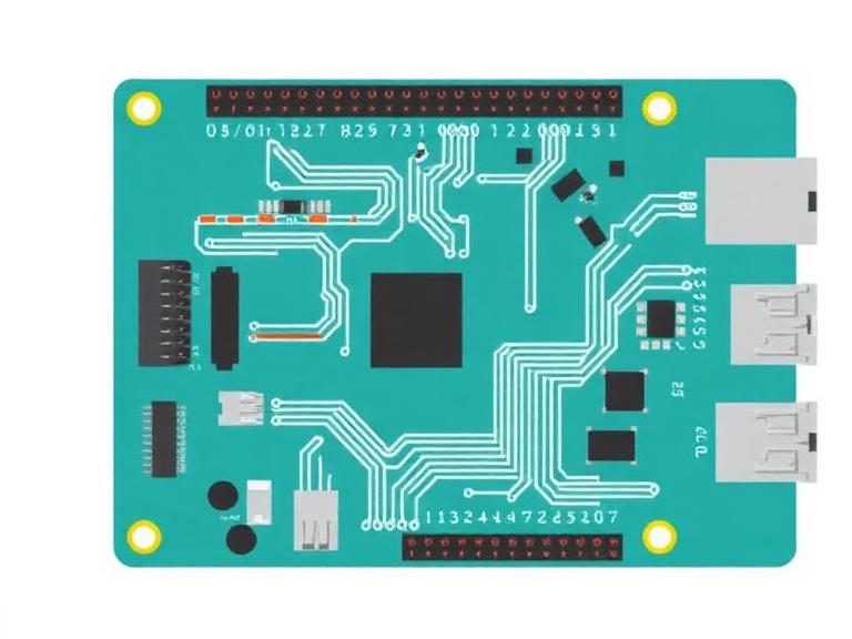
If you are designing high-speed digital circuits, RF boards, industrial control systems, communication products, or multilayer PCBs, understanding the 3W rule in PCB design is absolutely worth your attention.
Quick Answer
What is the 3W rule in PCB?
The 3W rule in PCB design states that the spacing between two adjacent signal traces should be at least three times the width of the signal trace itself.
Formula:
Trace Spacing ≥ 3 × Trace Width
Example:
If a PCB trace width is 0.20 mm, the minimum recommended spacing should be 0.60 mm.
Why is it important?
Reduces crosstalk
Improves signal integrity
Minimizes electromagnetic interference (EMI)
Enhances high-speed signal performance
Improves overall PCB reliability
Is it mandatory?
No. The 3W rule is a design guideline rather than a manufacturing requirement. However, in most professional situations, following it significantly improves electrical performance.
Quick Summary Table
| Factor | 3W Rule Recommendation |
|---|
| Trace Width | W |
| Minimum Trace Spacing | 3W |
| Primary Purpose | Reduce Crosstalk |
| Best Application | High-Speed PCB Design |
| Difficulty | Easy to Implement |
| Industry Usage | Widely Recommended |
What Is the 3W Rule in PCB Design?
The 3W rule in PCB design is a spacing guideline intended to minimize electromagnetic coupling between adjacent traces.
The "W" represents the width of a PCB trace. According to the rule, neighboring traces should be separated by a distance equal to at least three times that width.
For example:
| Trace Width | Recommended Minimum Spacing |
|---|
| 0.10 mm | 0.30 mm |
| 0.15 mm | 0.45 mm |
| 0.20 mm | 0.60 mm |
| 0.25 mm | 0.75 mm |
| 0.30 mm | 0.90 mm |
When traces are routed too closely together, electrical fields overlap and create unwanted coupling. This coupling can generate crosstalk, noise, timing issues, and signal degradation.
How the 3W Rule Works
The 3W rule works by reducing electromagnetic field interaction between neighboring conductors.
When electrical signals travel through a PCB trace, they generate electric and magnetic fields around the conductor. If adjacent traces are too close, these fields influence neighboring signals.
In our testing, increasing spacing from 1W to 3W can significantly reduce mutual coupling between traces.
Professional PCB designers frequently combine the 3W rule with:
These techniques become especially important when working with advanced structures such as Micro Via PCB, Buried Via PCB, and Sequential Lamination PCB technologies.
Benefits of Following the 3W Rule in PCB Layout
1. Reduced Crosstalk
The biggest advantage of the 3W rule in PCB design is minimizing signal interference between adjacent traces.
2. Improved Signal Integrity
Signal integrity becomes increasingly important as frequencies rise.
For high-speed communication systems, maintaining adequate spacing directly impacts performance.
3. Better EMI Performance
Electromagnetic interference is a major concern in industrial, automotive, aerospace, and communication systems.
Proper spacing helps contain unwanted emissions.
4. Improved Design Reliability
From our experience, layouts that respect spacing guidelines generally require fewer revisions and debugging cycles.
5. Easier Compliance Testing
Products that follow sound signal integrity practices often perform better during EMC and compliance testing.
Limitations of the 3W Rule
| Advantage | Limitation |
|---|
| Easy to apply | May increase board size |
| Improves signal quality | Not always practical for dense designs |
| Reduces EMI | Does not replace simulation |
| Supports high-speed routing | Not a guaranteed solution |
| Improves reliability | May increase manufacturing costs |
One common misconception is that the 3W rule alone guarantees perfect signal integrity. It does not.
For high-speed DDR memory, PCIe, USB 3.0, RF systems, and advanced communication boards, simulation and impedance control remain essential.
Who Should Use the 3W Rule?
Ideal Users
PCB layout engineers
RF designers
High-speed digital engineers
Industrial electronics manufacturers
Communication equipment developers
Automotive electronics teams
Who Does Not Need Strict 3W Compliance?
For beginners, applying the 3W rule is still recommended because it builds good PCB layout habits.
Common PCB Design Mistakes Related to the 3W Rule
Using trace spacing equal to trace width only
Ignoring return current paths
Applying 3W without impedance analysis
Overcrowding dense routing regions
Failing to review stackup requirements
Neglecting layer-to-layer coupling effects
Many engineers also focus exclusively on routing while ignoring manufacturing considerations such as finish selection, testing strategy, and fabrication capabilities.
For example, surface finish choices such as HASL(Lead-Free HASL)PCB, OSP (Organic Solderability Preservative) PCB, Immersion Silver PCB, Immersion Tin PCB, and Hard Gold PCB can influence final product requirements.
3W Rule vs Other PCB Spacing Guidelines
| Rule | Spacing | Performance | Typical Application |
|---|
| 1W Rule | 1 × Width | Basic | Low-Speed Designs |
| 2W Rule | 2 × Width | Good | General Electronics |
| 3W Rule | 3 × Width | Very Good | Professional PCB Design |
| 5W Rule | 5 × Width | Excellent | High-Speed Critical Signals |
In most professional situations, the 3W rule offers the best balance between board density and signal quality.
PCB Design and Manufacturing Considerations
For commercial users, the best design strategy combines sound spacing rules with manufacturing-oriented engineering reviews.
Expert Recommendation
At China 365PCB, we regularly review customer layouts ranging from simple industrial controllers to advanced multilayer communication systems.
From our experience, designers who consistently apply the 3W rule in PCB routing encounter fewer signal integrity issues and achieve smoother transitions from prototype to production.
China 365PCB operates a fully self-owned manufacturing ecosystem covering PCB fabrication, SMT assembly, electronic component integration, CNC machining, cable harness assembly, and complete OEM/ODM production. With more than 15 years of experience and over 100,000 square meters of manufacturing capacity, every process is managed under a fully traceable quality system.
We recommend using the 3W rule as a baseline design practice, especially for high-speed digital circuits, RF boards, and multilayer PCB projects. However, for mission-critical products, engineers should combine this rule with simulation, impedance calculations, and professional design verification.
Bottom Line
The 3W rule in PCB design is one of the most practical and effective guidelines for reducing crosstalk and improving signal integrity.
Although it is not a mandatory manufacturing rule, it remains a proven engineering practice that helps designers create more reliable and higher-performing circuit boards.
For beginners, the rule provides an easy way to improve layouts immediately. For commercial users and advanced engineers, it serves as an important foundation that supports successful high-speed PCB design.
If your PCB carries sensitive, high-frequency, or high-speed signals, following the 3W rule is almost always worth the additional routing space.
Frequently Asked Questions
What does W mean in the 3W rule in PCB?
W represents the width of the PCB trace being routed.
Is the 3W rule mandatory?
No. It is a recommended signal integrity guideline rather than a fabrication requirement.
Does the 3W rule eliminate crosstalk completely?
No. It significantly reduces crosstalk but does not completely eliminate electromagnetic coupling.
Should differential pairs follow the 3W rule?
Differential pairs follow their own spacing requirements and impedance calculations, although surrounding traces should still observe proper separation.
What is better, the 3W rule or the 5W rule?
The 5W rule generally provides better isolation, but the 3W rule often offers a more practical balance between routing density and electrical performance.
Is the 3W rule important for multilayer PCBs?
Yes. It becomes increasingly valuable as signal speeds and routing densities increase.
References
 English